uTailLight
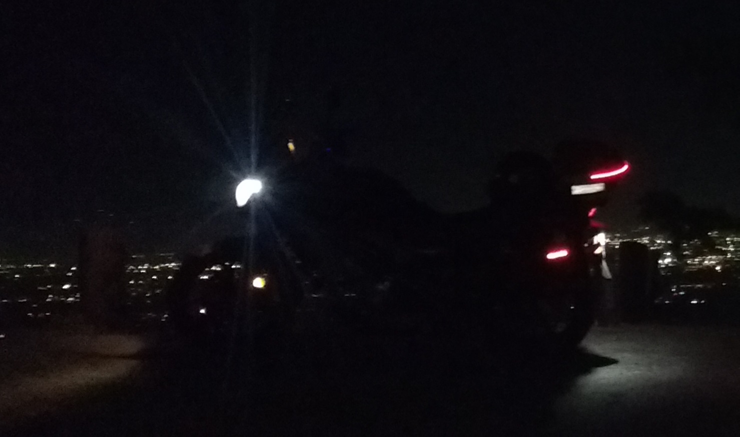
This summer I started riding a motorcycle, and while stuck at home, I designed and built an auxiliary LED indicator system for added visibility. The system uses addressable LEDs, allowing the compact controller with an integrated power supply to manage potentially hundreds of LEDs.
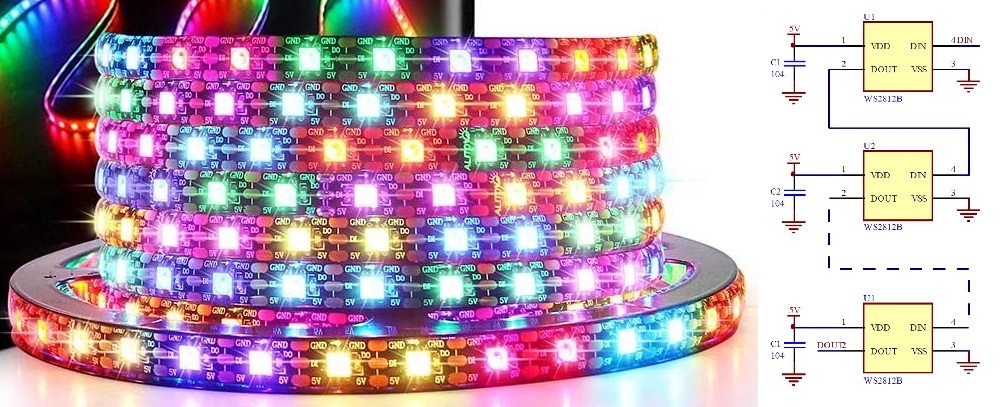
The system is based on WS2812B addressable RGB LEDs. The LEDs operate using a daisy-chained communication protocol, where the first LED will grab the first LED worth of data, then forward the rest of the configuration data to the next LED. The cycle repeats until all LEDs have their configuration data. I purchased a 5M roll of 60LED/M tape which has a IP65 rating thanks to a silicone coating.
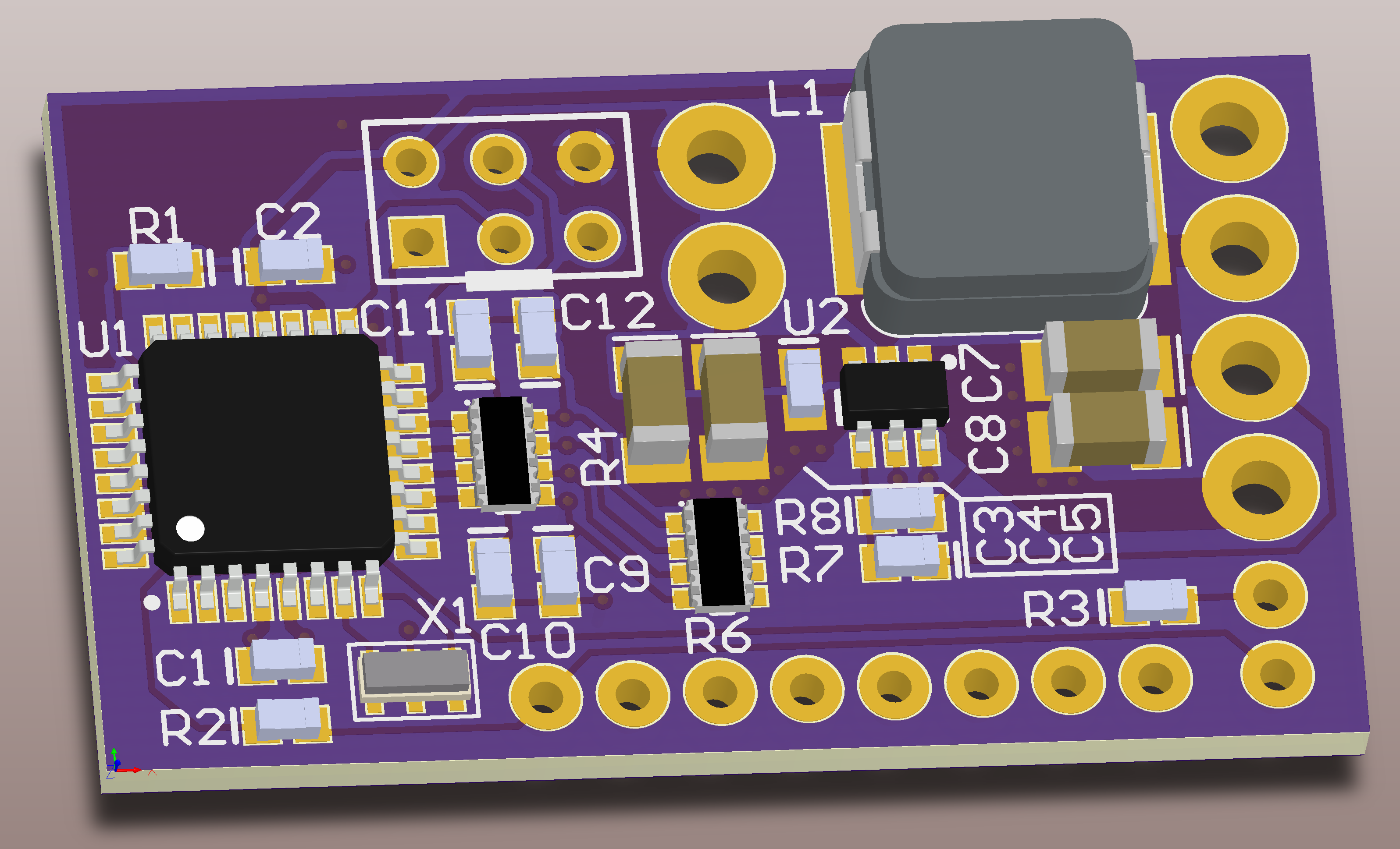
The tiny board, at 0.85” x 1.44”, is capable of supplying 5V at up to 5A. This is theoretically enough for more than 150 LEDs with 100% output on all RGB channels. Practically speaking, since only approximately half of the LEDs are in use at one time and white is rarely used, substantially more LEDs can be driven in this application. The controller has two outputs, for two LED strings, but only one was used for now.
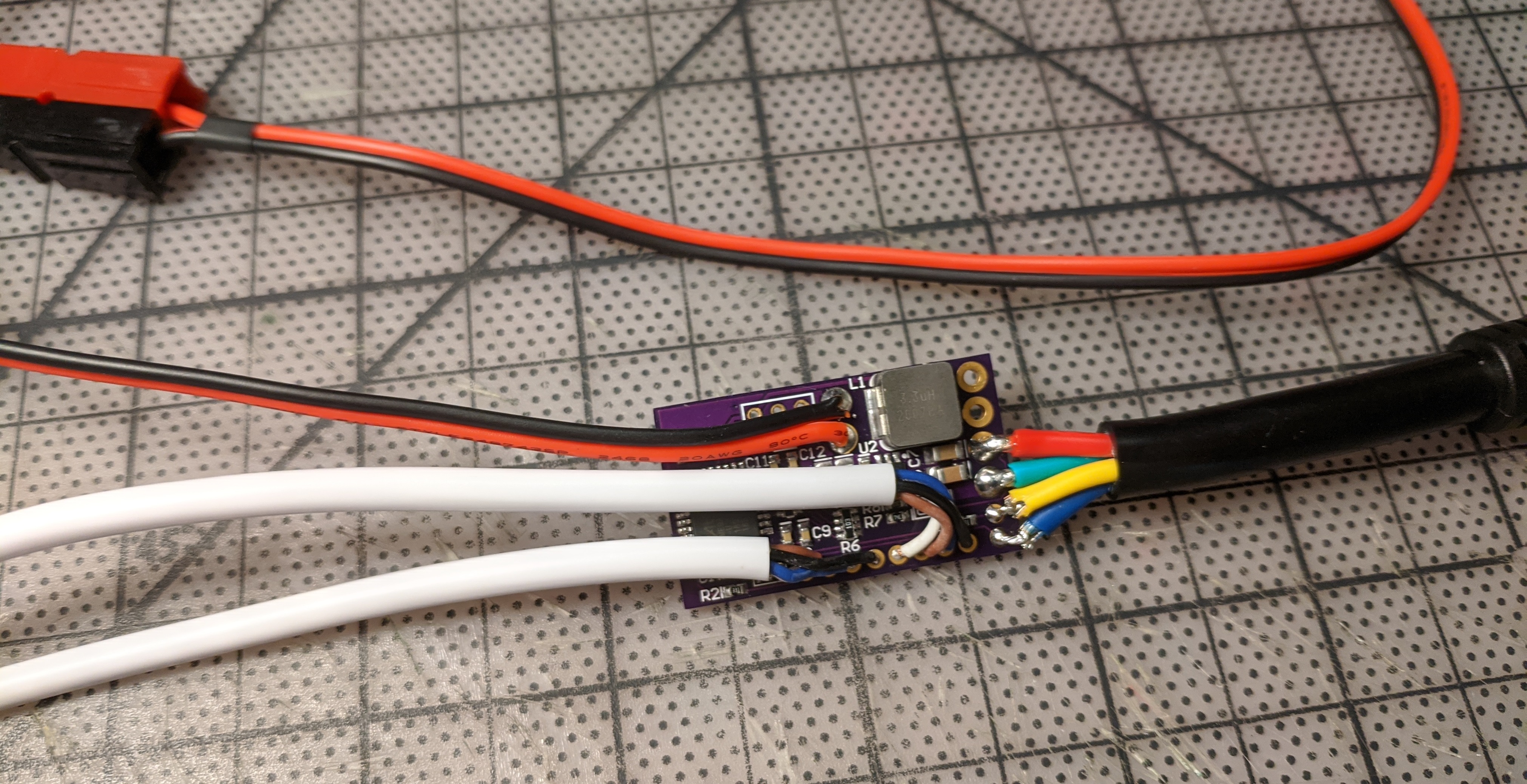
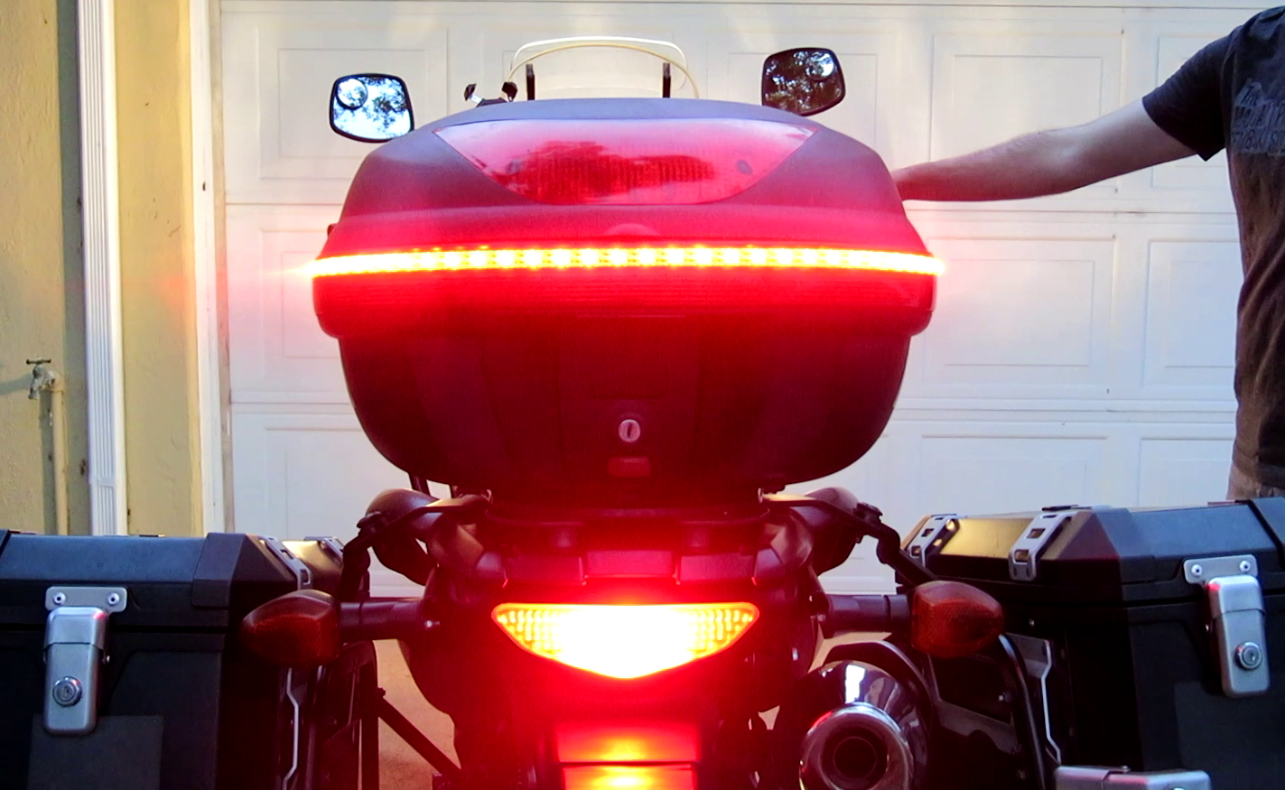
The controller has 4 inputs which are used for detecting left, right, brake, and a user input switch (mounted on handlebars). The final PWA uses an Anderson Powerpole for 6.5-16V power input, and waterproof connectors for programming, trigger inputs, and LED outputs. The board was conformal coated and enclosed by hot-glue filled heat shrink tubing, which also functioned as strain relief for the harnessing. The LED strips used on the front hand guards and rear top case were all configured as a continuous strip, with the serial data output of each strip being connected to the input of the next (allowing only one WS2812B output data line from the MCU to be used).
For tapping into the left, right, and brake lines on the bike, I found the connector used for the taillight harness, and manufactured a small harness that goes between the main and tail harnesses, allowing me to access the lines feeding the rear bulbs without modifying any of the original harnessing.
A series of finite state machines (run at 60Hz) are used to manage the inputs (debouncing, short/long press, etc.), coordinate indicating/braking animations, and other animations (hazards, etc.). Animation parameters, such as timing, colors, LED positions, can all be easily updated for adapting the system to any specific LED tape layout.
The hazard animation can be activated/deactivated using the bike’s built in hazards (detected by monitoring the left and right indicator lines), or by a long press (or holding) on the user switch on the handlebars. Short presses on the switch cycles the animations such as amber, amber/white and amber/red, blue, etc.