
Animation System Main Computer
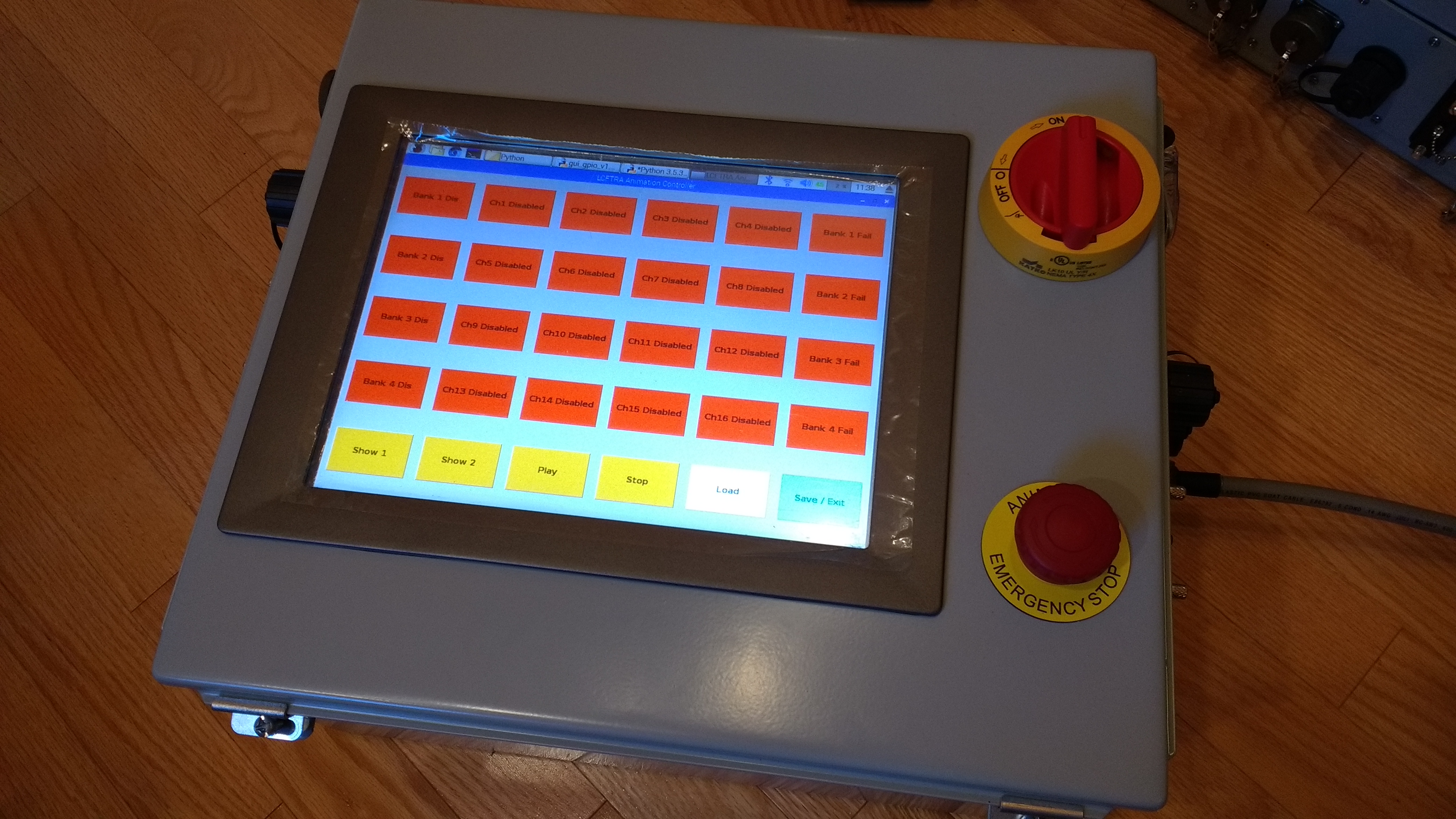
The new La Cañada Flintridge Rose Parade float’s animation system has a controller unlike anything used in the parade. The custom controller has a 12 inch waterproof touchscreen that sports a custom control GUI and convenient system configuration capabilities.
The animation computer contains the main show controller and various support hardware. The “animation computer” hasn’t traditionally used what we would think of as a computer, but has rather been an assembly of custom or commerical off-the-shelf industrial control hardware (at least in the case of the La Cañada float). This animation computer actually contains a computer, however, it only serves to control dedicated show control hardware. To see how the main computer fits in to the animation system, check out this summary of the new animation system.
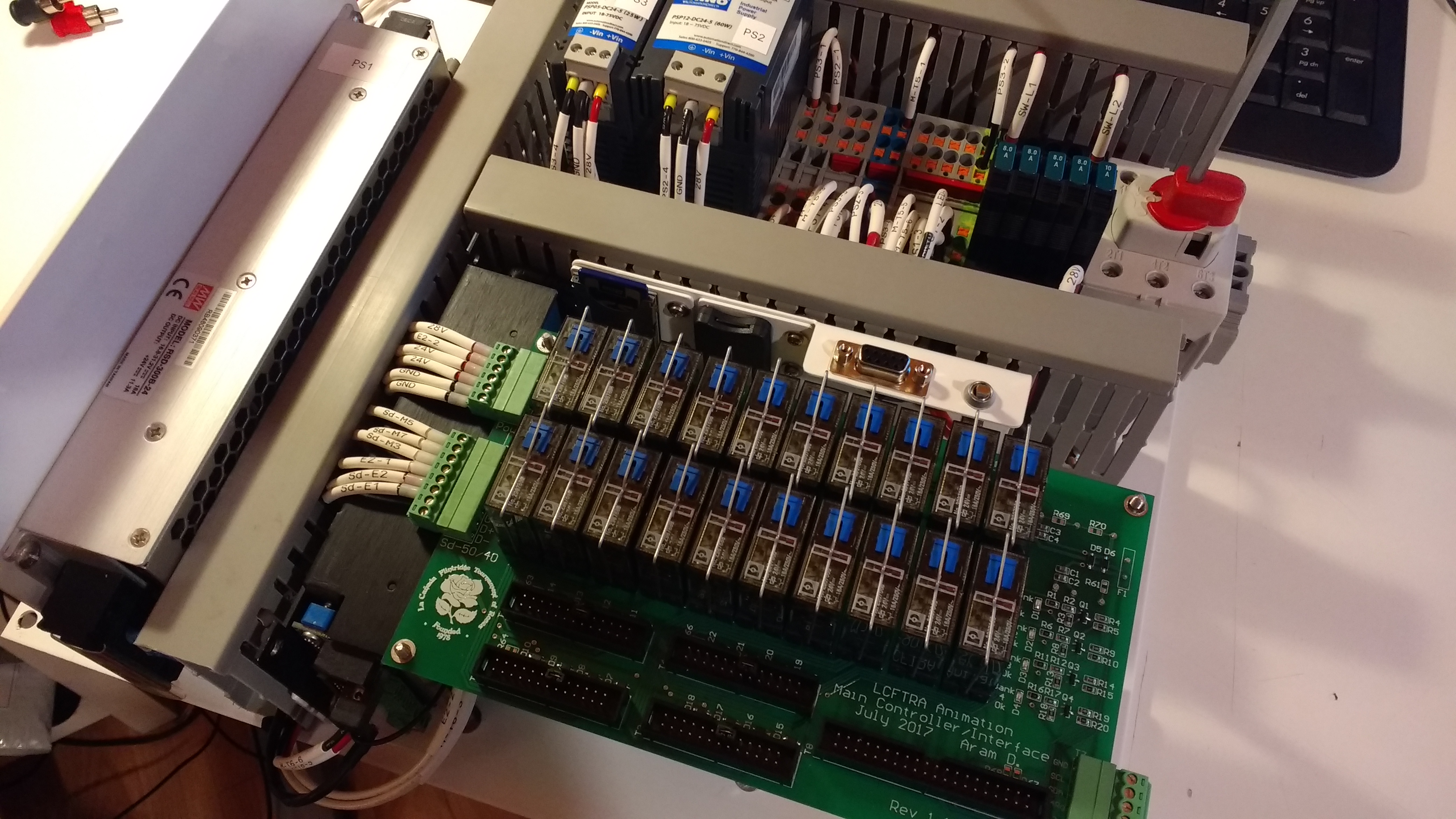
At the heart of the system is a controller/inerfacing PCB assembly. This board is responsible for controlling the main Gilderfluke Sd-50/40 show controller, as well as interfacing with the four Br-EFB PID controllers and 16 Rexroth proportional valve drivers.
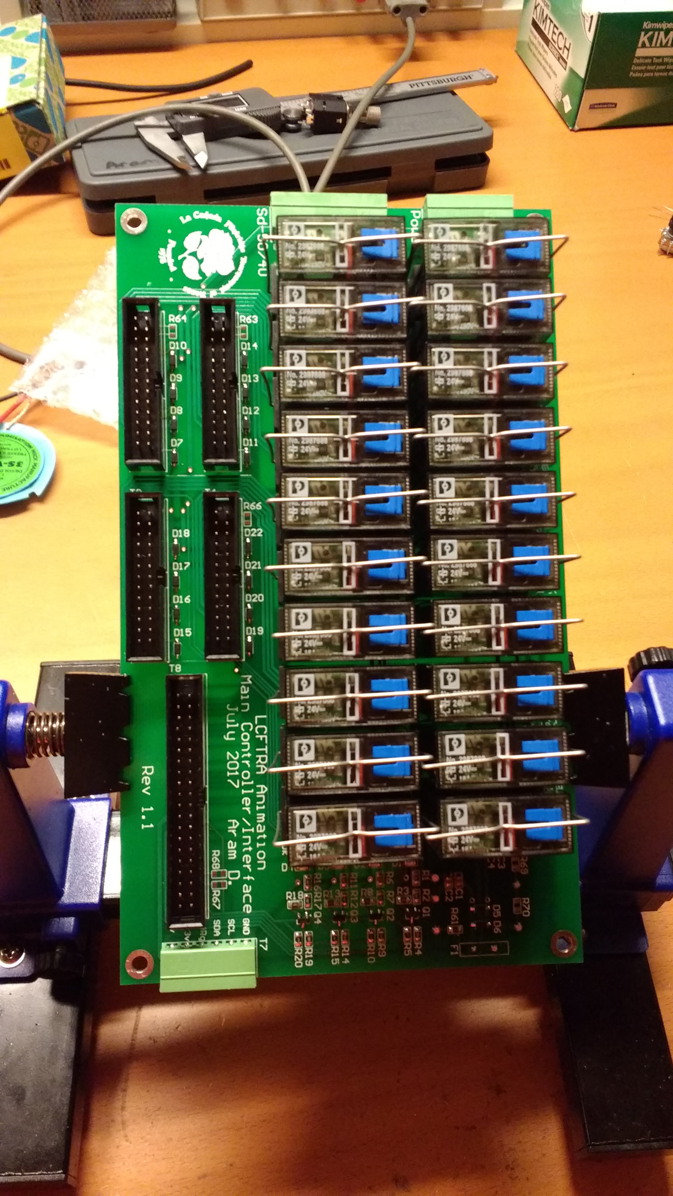
The PCBA consists of 20 relays (with manual actuation tabs which serve as a manual backup), connectors for power, the Sd-50/40, and each valve bank box, as well as a 5 volt power supply for the Raspberry Pi which runs the controller via the GUI.
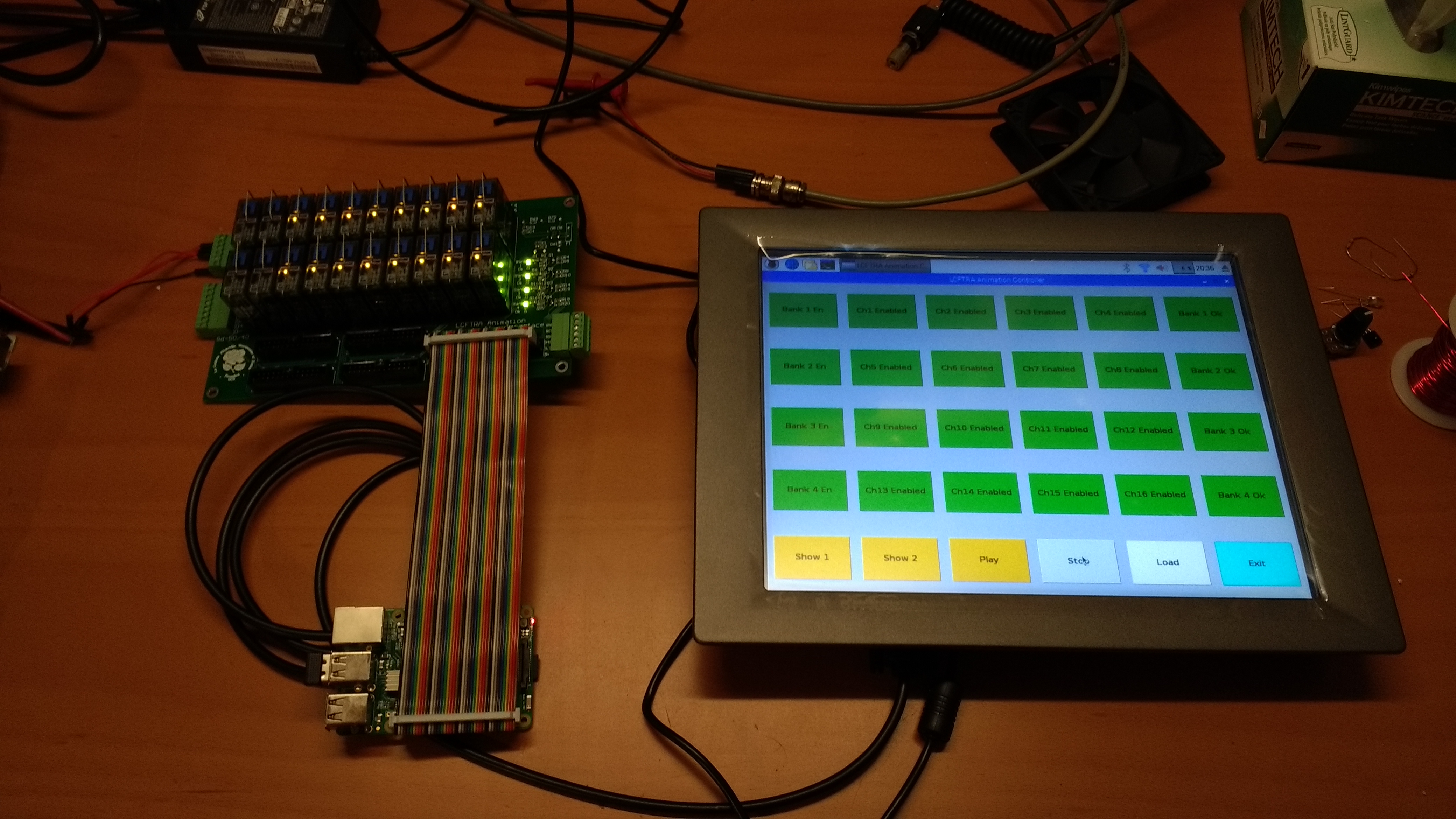
The GUI, written in Python, allows the animation operator to control the Sd-50/40 show controller, enable/disable each valve driver individually, as well as provide a health status for each Br-EFB. The GUI has a number of customizable parameters to aid the animation operator such as configurable labels (descriptive names instead of channel numbers), customizable device configuration loading, and more.
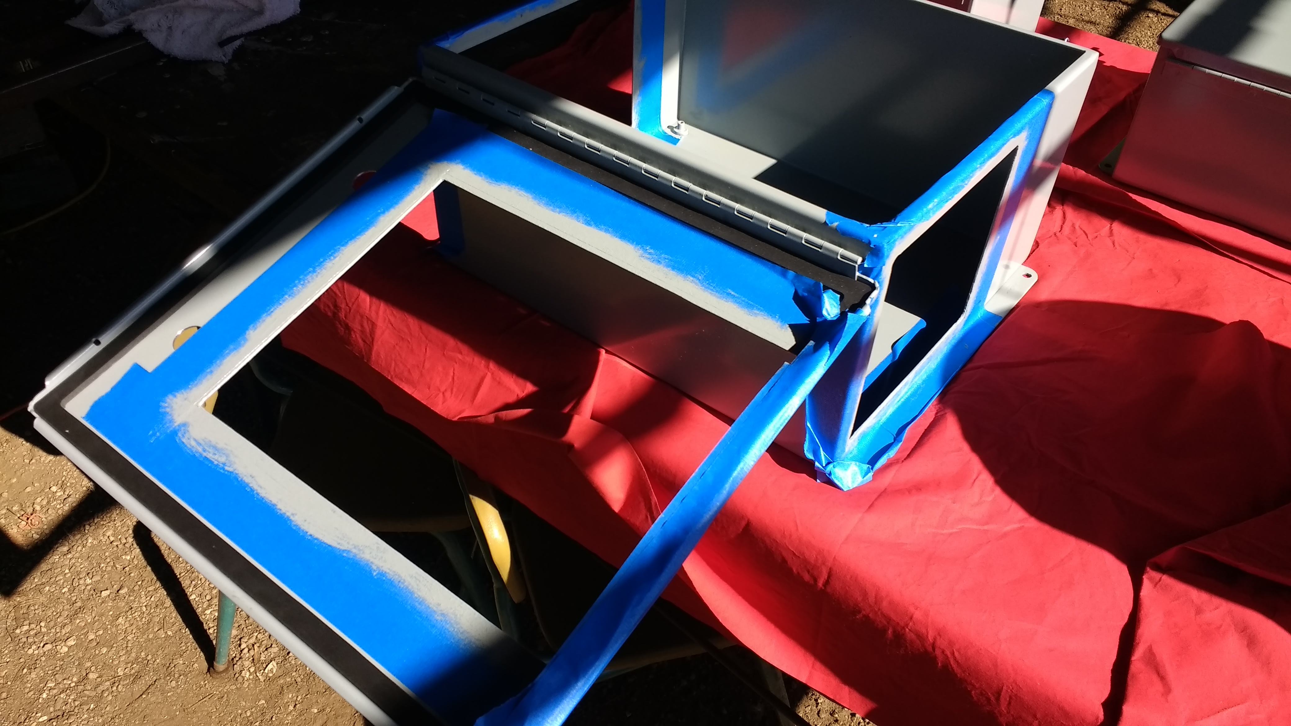
Now of course all of this has to be packaged in a suitable enclosure. Just like the valve bank modules, the connectors on the box will be mounted on powder-coated custom waterjet cut plates. Three large rectangular openings were cut in the animation controller box for the two connector plates and the touchscreen. The exposed metal on all of the boxes was painted with matching ANSI 61 gray paint.
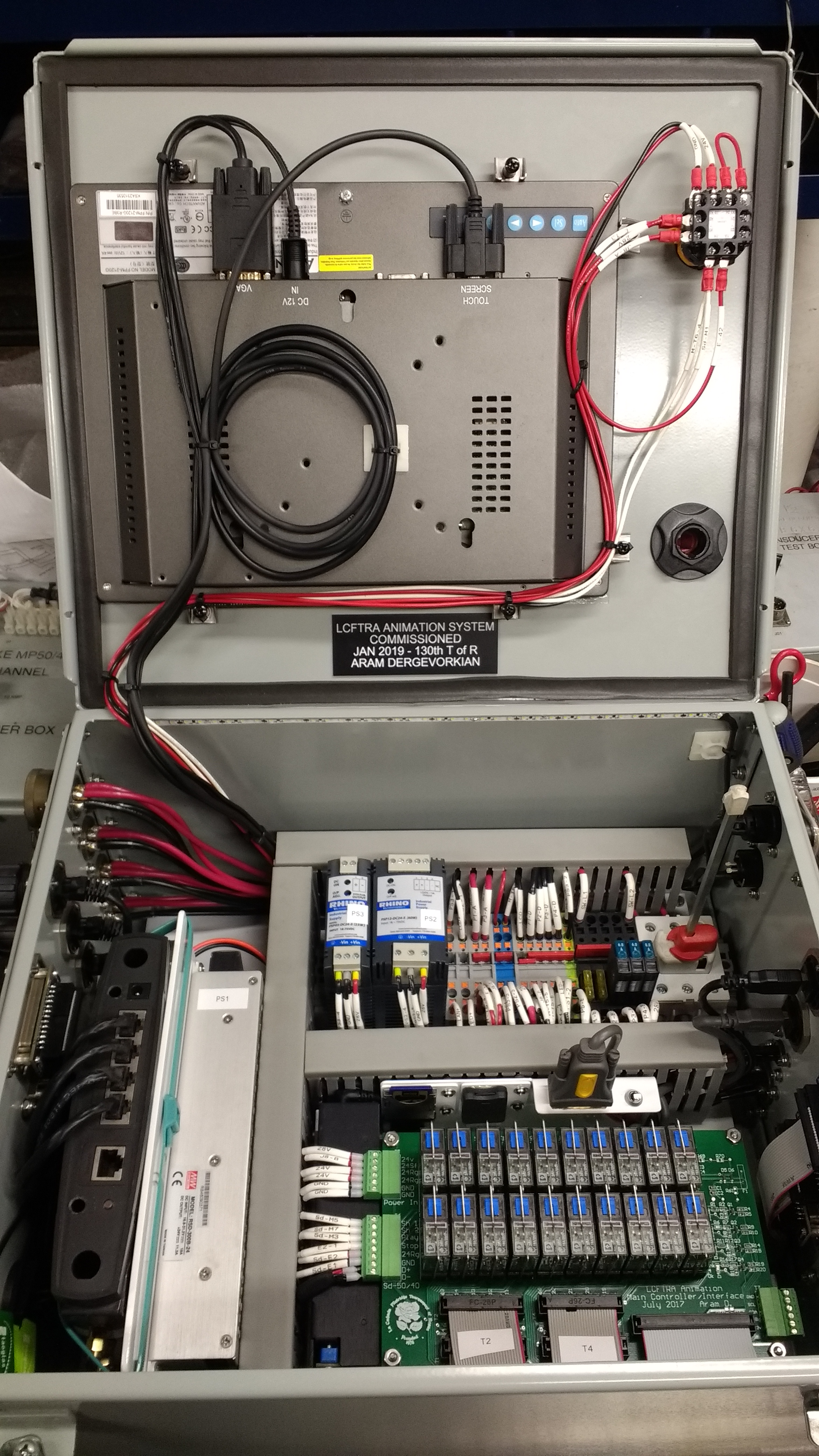
The touchscreen, emergency stop button, and power switch actuator are mounted to the lid of the enclosure. The system’s power switch functions as a safety lockout; the unit can not be opened while power is on. The switch also accommodates three lockout-tagout locks which prevent the controller from being turned on or opened.
The lower half of the animation computer contains several power supplies, the Gilderfluke Sd-50/40 show controller, the Raspberry Pi and controller/interface PCBA, router, and DC distribution hardware.
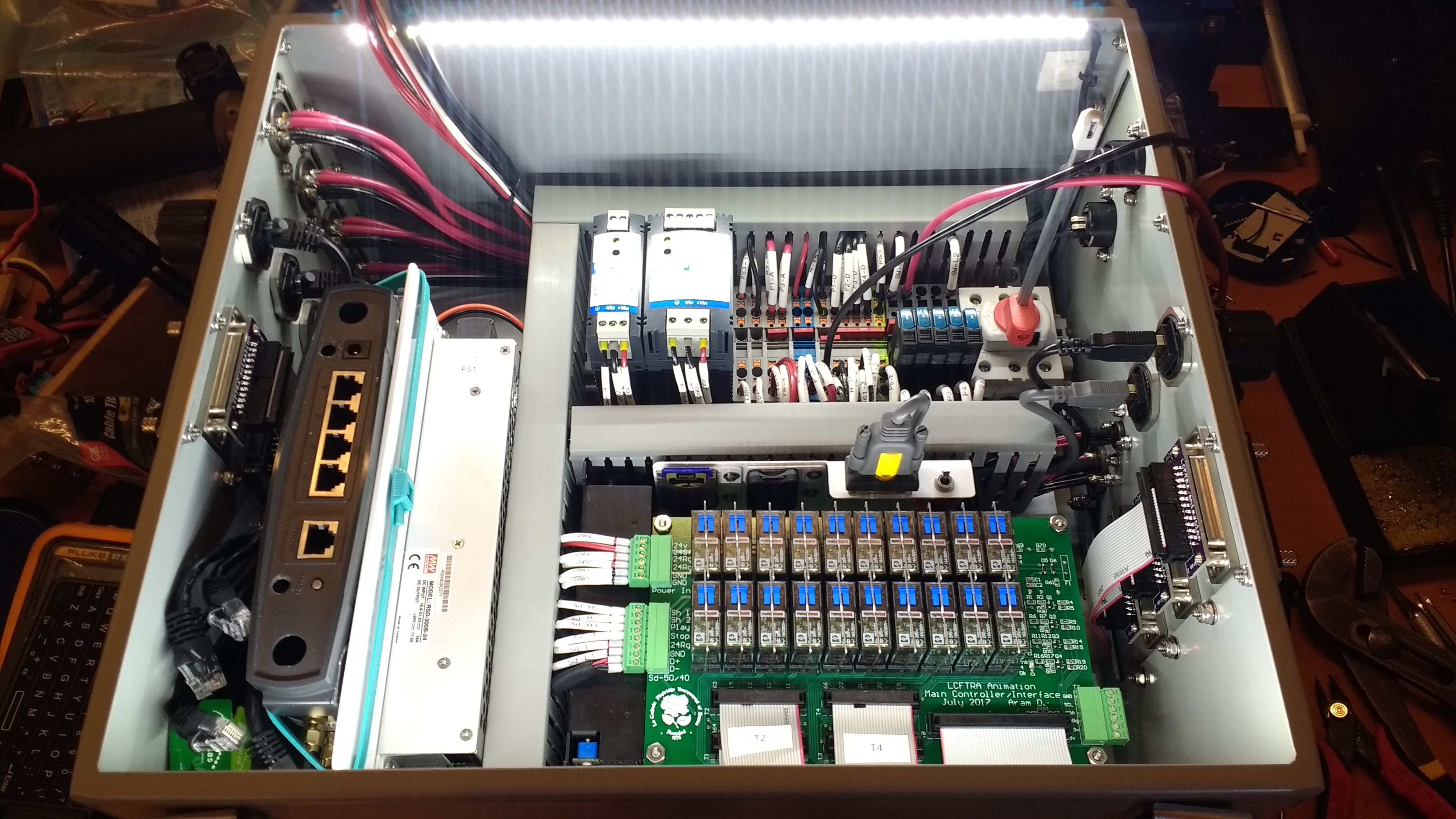
Yes, I know what you’re thinking; that does look awfully compact. We could have chosen a larger enclosure, but since this unit has to be installed in potentially small crew compartments and must be easy to install and remove, we decided to go with as cozy of an enclosure as possible.
The animation system has since successfully been down the parade route! The float, Tree Frog Night, featured 3 frog musicians and an accompanying cast of dancing fish. For an overview of the animation system’s debut, check out this page.