
Integrated Accessory Controller
Following my previous project involving accessing my car’s CAN bus, I wanted to take CAN control further by making a custom controller that can interface with a vehicle to control various accessories.
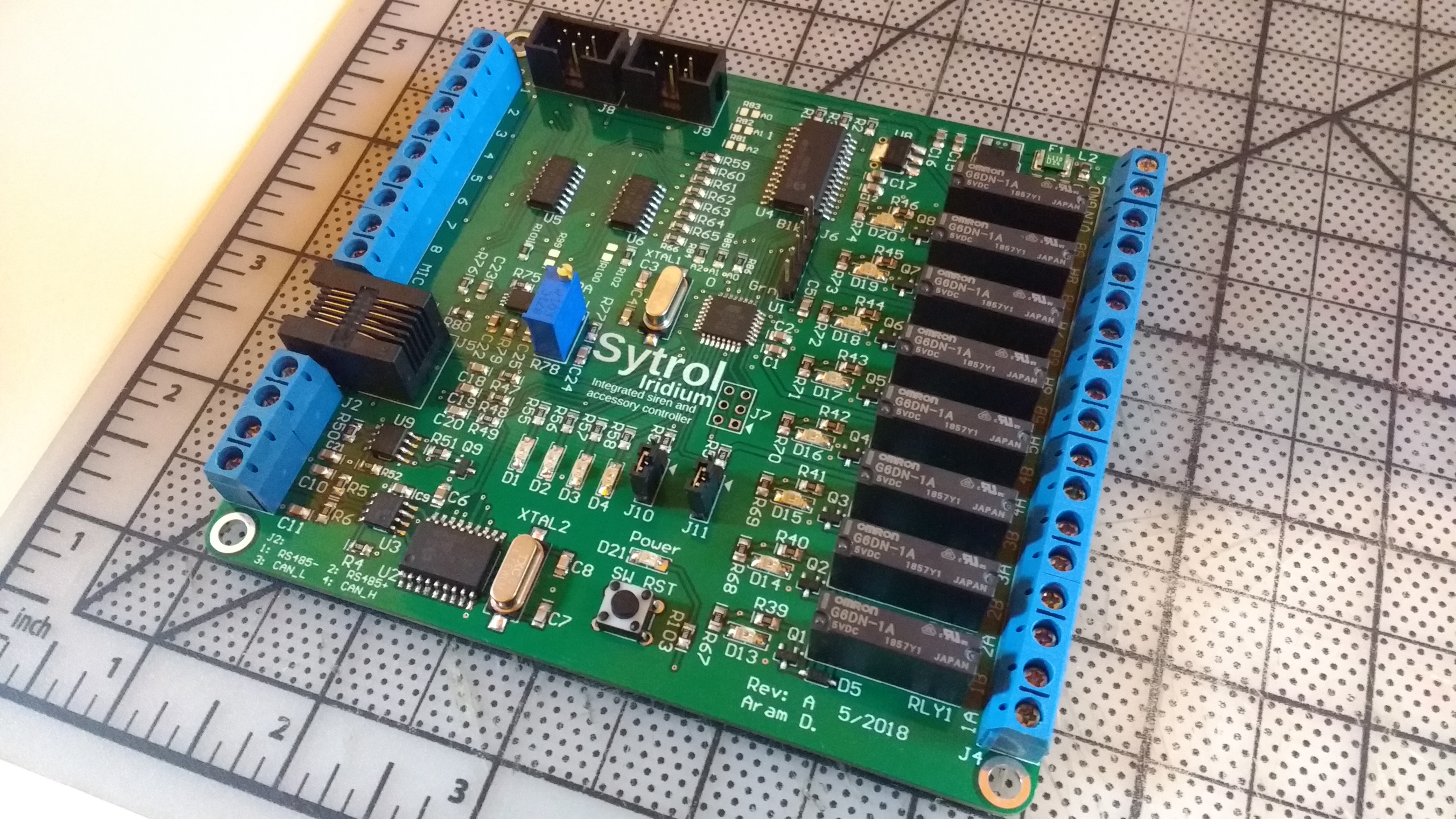
I subsequently started designing this printed circuit board. This unit integrates:
- A CAN interface
- A RS-485 interface (frequently used by remote mounted emergency vehicle equipment such as remote siren amplifiers)
- Interfacing for a Yaesu MH-48 handheld microphone with a DTMF keypad
- 8x optical isolators for low current accessories (such as contact closure inputs on equipment)
- 8x SPST relays rated at 5A for powering various accessories
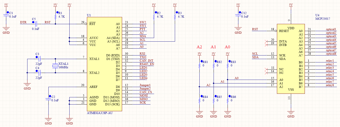
At the heart of the unit is an atmega328 operating as an Arduino, and a MCP23017 I2C expander IC. The Arduino can interface with devices over I2C, CAN bus, RS-485, or receive user input through the MH-48 microphone. Depending on how the unit is programmed, the Arduino can switch relays, activate opto-isolators, or generate CAN bus or RS-485 data.
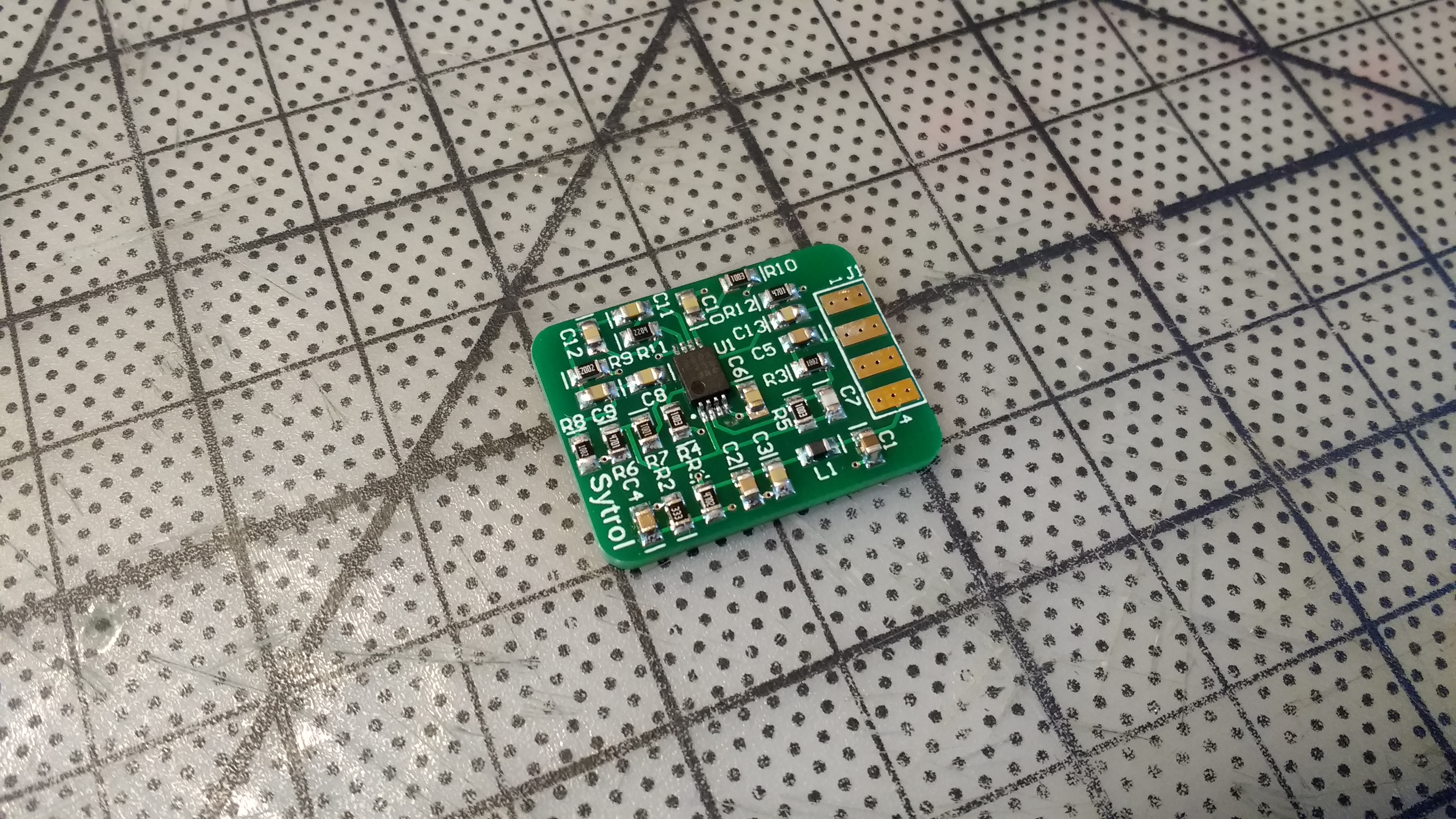
To allow the use of the MH-48 as a microphone for a public address (PA) system, a small amplifier is needed within the microphone. Usually, the head unit of a mobile radio is mounted in the front of the car, and amplifies the low level audio signal being generated by the mic before it travels to wherever the actual transceiver is mounted. Since the audio signal travelling through the car is very large, its less prone to picking up electronic interference which would lead to noisy audio.
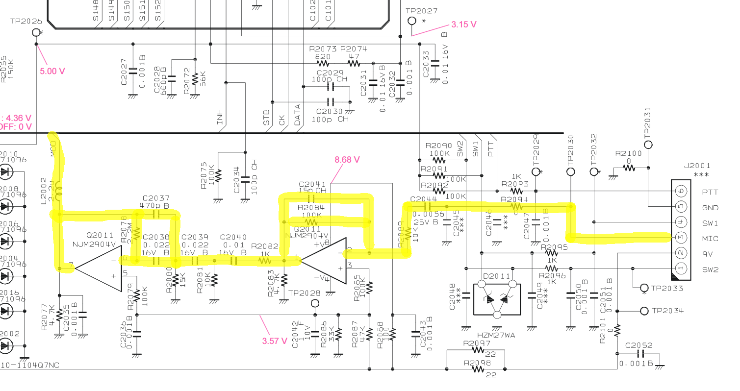
As you can see, the Yaesu FT-7900r (a common mobile radio that uses the MH-48 mic) feeds the incoming audio from the microphone into a set of op-amps that boost the voltage of the signal up significantly.
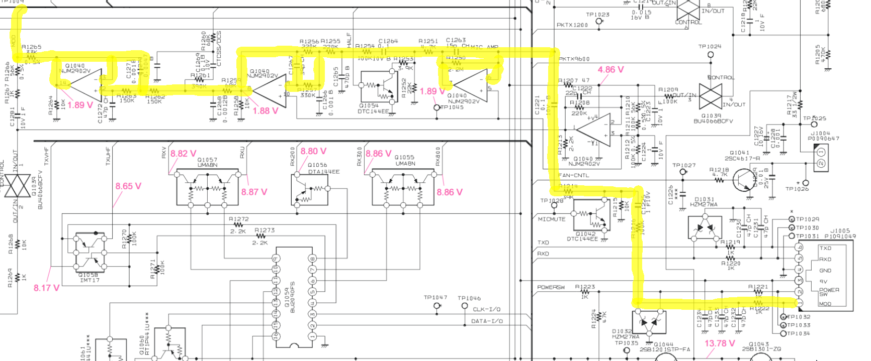
When the audio reaches the FT-7900 transceiver, another set of op-amps decreases the level of the signal to whatever is required to properly modulate the transmitter.
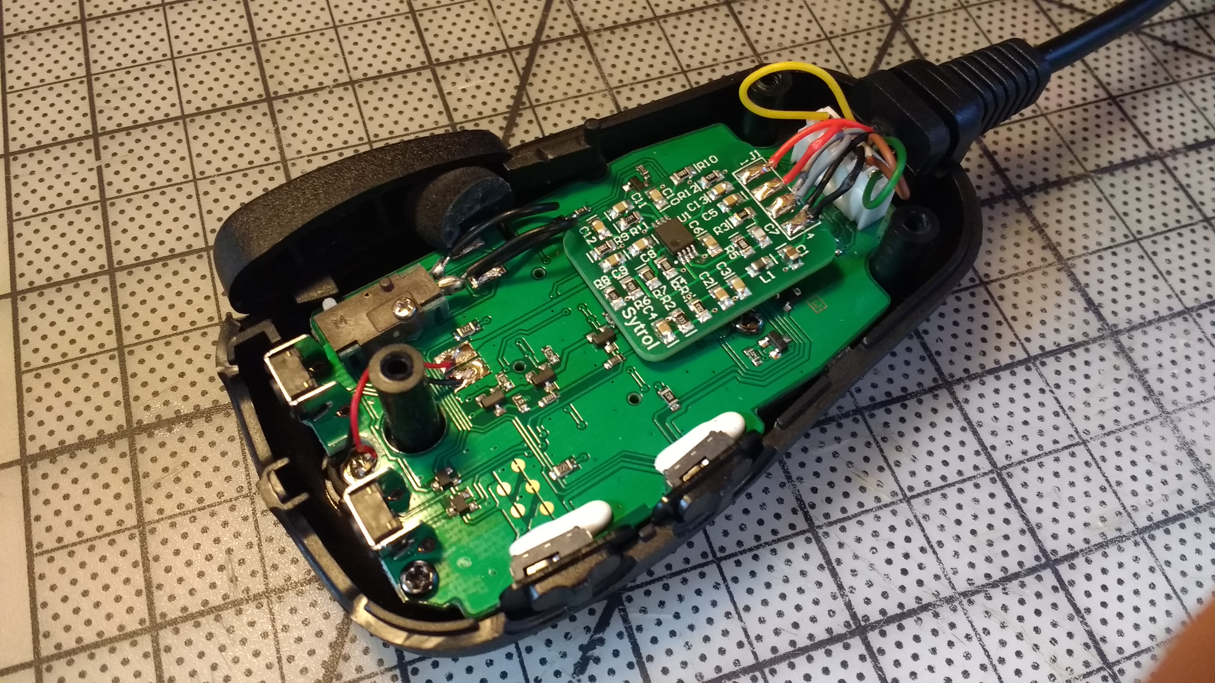
The main PCB has been assembled and initial programming has started. The microphone has been modified (shown above), and tested to work properly. Software development is under way, but will require more time before this unit is ready for field (or vehicle) testing.