The McMaster-Car - a 7.5" Gauge E-Bike Pedal Car
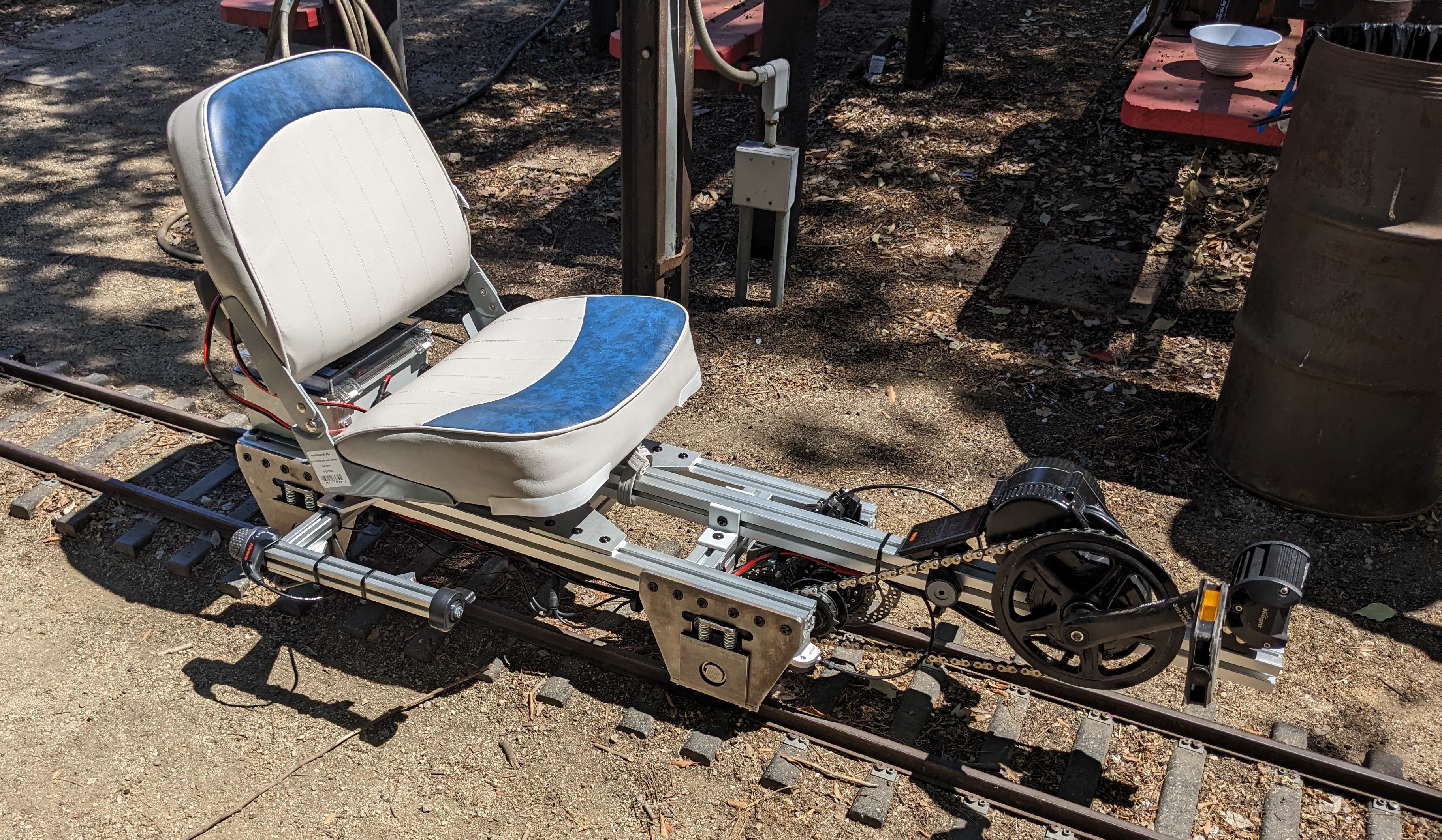
About a year ago, I began volunteering at the Los Angeles Live Steamers Railroad Museum, and quickly felt the need to build myself a train to zip around the club’s ~1.5 miles of track located in the picturesque northeast corner of Griffith Park. Rather than build a prototypical locomotive, I decided to make what’s commonly referred to as a “pedal car” with some unique features.
Rather than make the whole frame out of raw stock which I would have to machine, bend, weld, etc. I went with a more modular approach using “80/20” 1.5” square extruded aluminum. Instead of completely relying on human pedal power, I decided to use a Bafang BBS02 750W mid-drive motor kit meant for e-bikes. This e-bike motor can both provide pedal assist, or completely power the locomotive. Between these two design decisions, I hoped to circumvent the typical complex machining required to build either a pedal car or small electric “speeder” locomotive. This propensity to COTS (commercial-off-the-shelf) parts led me to name this locomotive the McMaster-Car, after McMaster-Carr, a well established online marketplace for all sorts of industrial components.
Before we get too far, I was lucky enough to be testing this at LALS when Lisa of Lisa K Entertainment on youtube was visiting the club. She took the McMaster-Car on a spin around the track and released this great video (in addition to two more focused on LALS and the public train rides we conduct on Sundays)!
Let’s start at the suspension. This is one of the components where machining was unavoidable, however, I was able to save quite a lot of time by using the Caltech Jim Hall design lab’s Flow Mach 2B waterjet to cut some components.
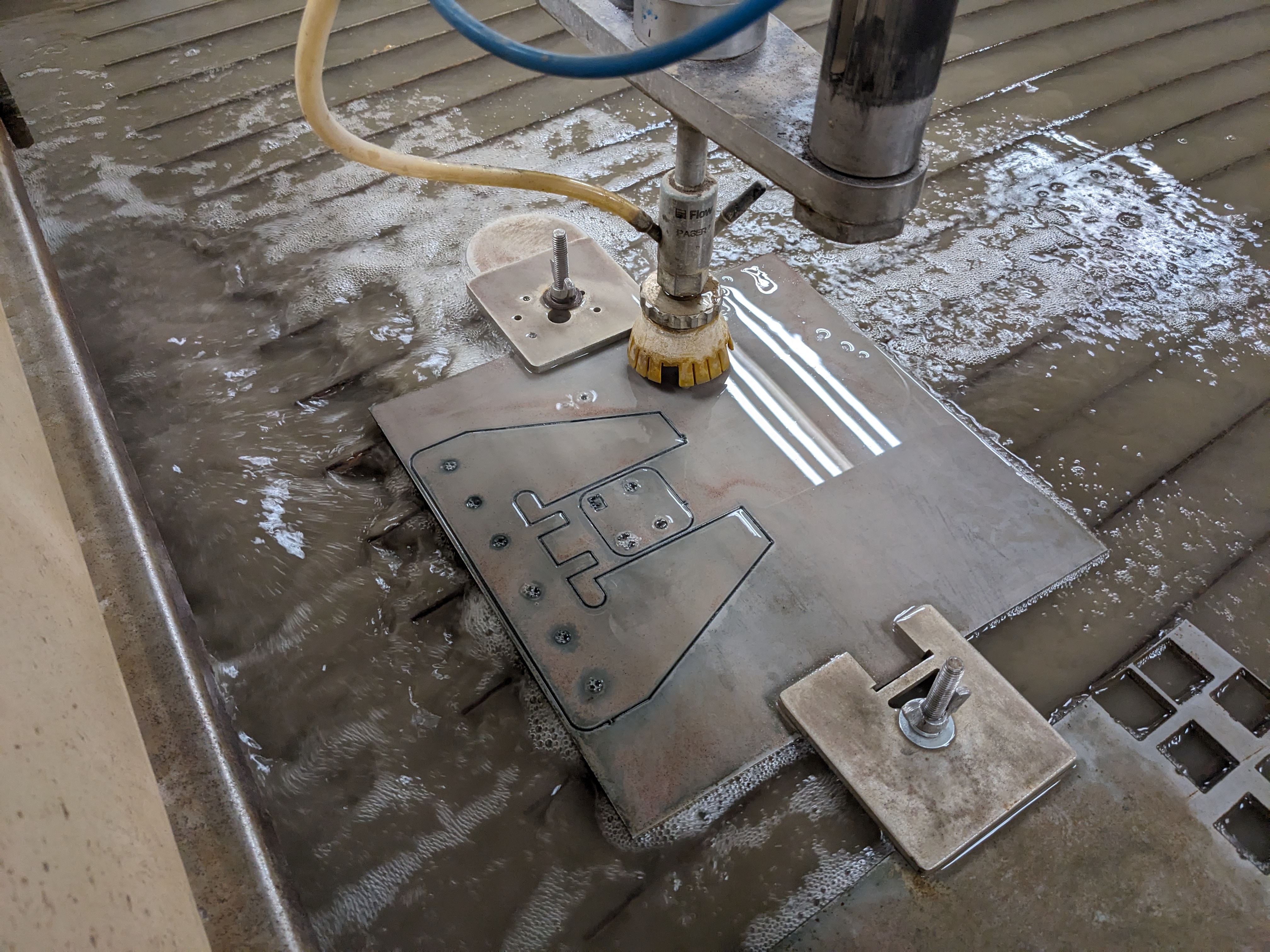
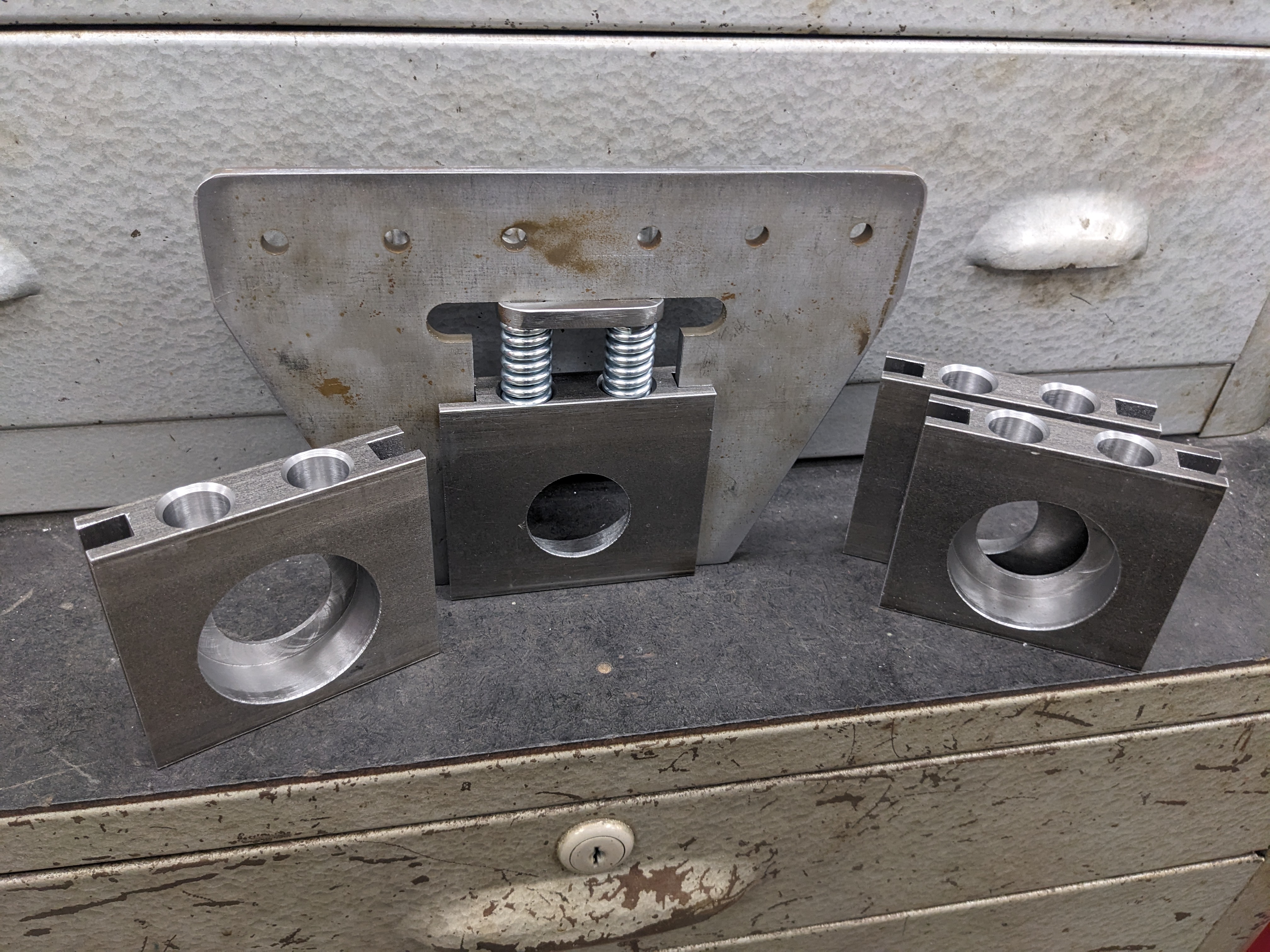
After waterjetting the plates, the only operations needed were to machine the parallel flat surfaces and chamfer the posts which are used to align the springs. The bearing blocks, however, needed to be machined manually… mostly. While I machine most of this by hand, I was able to machine the bearing pockets using a Bridgeport mill outfitted with a ProtoTRAK conversational CNC controller.
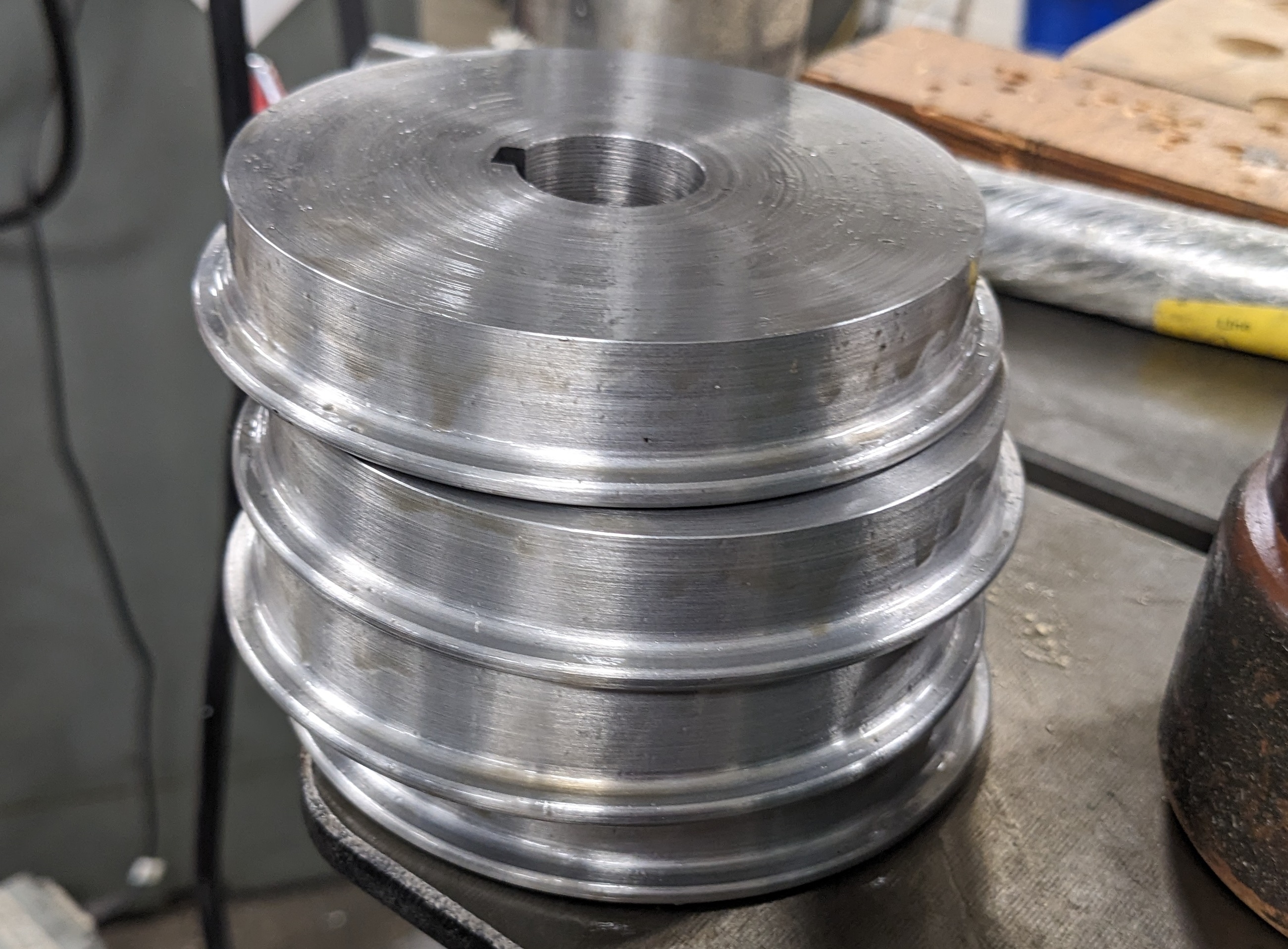
Thankfully, I was also able to use a lathe outfitted with a similar ProtoTRAK controller to machine the 4” (contact diameter) wheels per the International Brotherhood of Live Steamers wheel specification. I also broached a keyway into the wheels for indexing them on the locomotive’s two 1” axles.
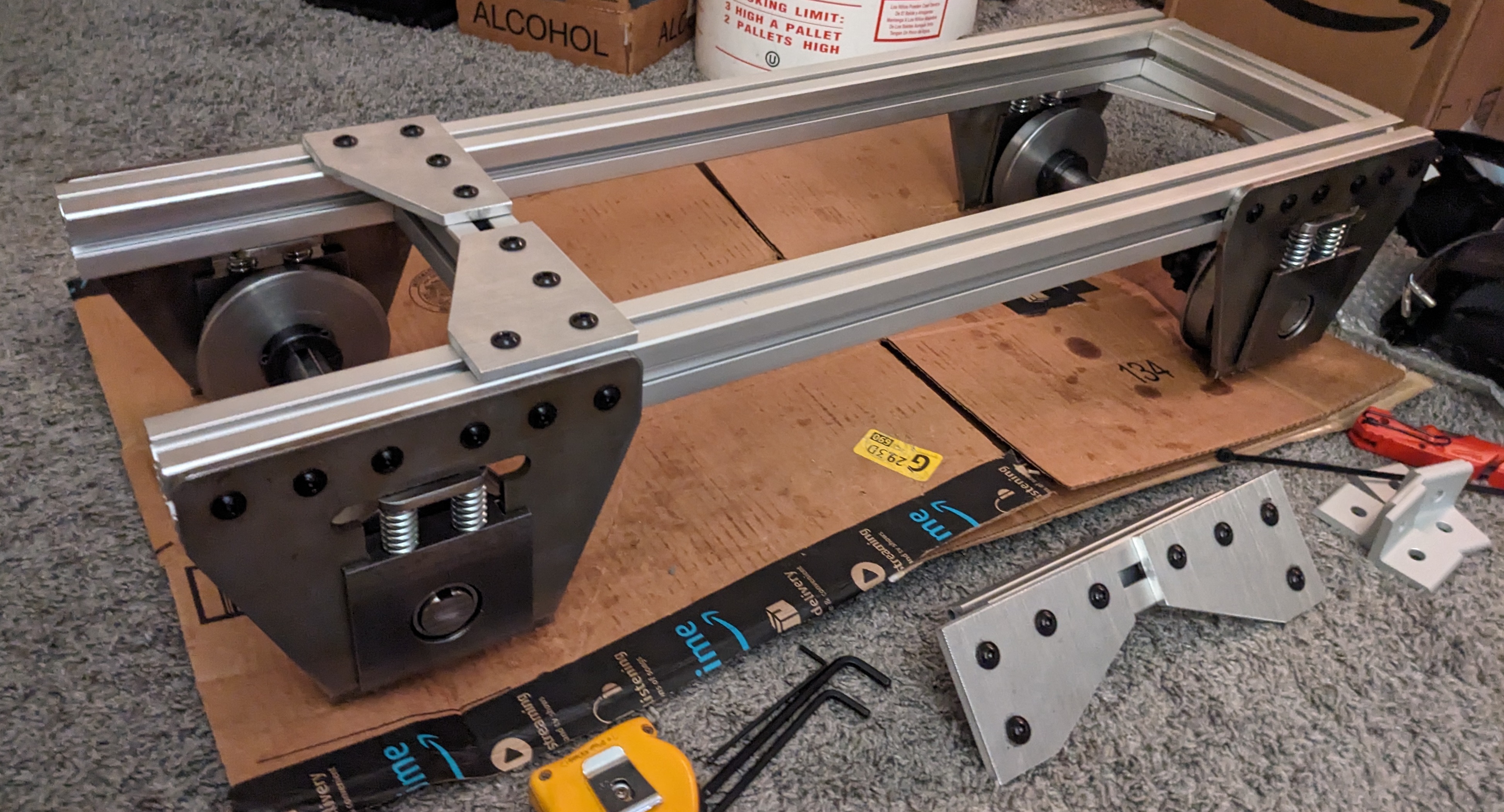
With the suspension and wheels done, the frame can begin to take shape. Rather than buying most of the interconnecting plates for the extruded aluminum, I was able to simply waterjet them out of scrap aluminum material very easily using existing CAD drawings I found online.
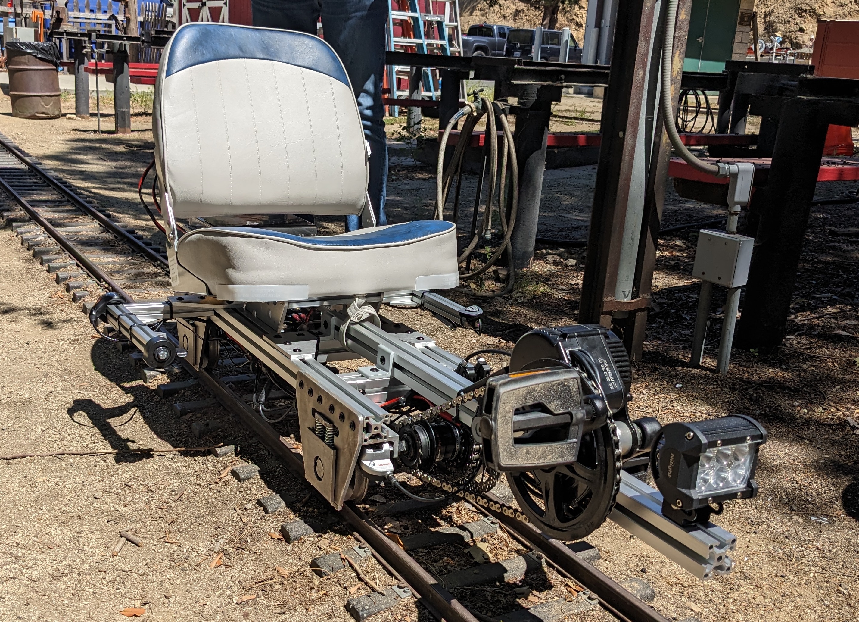
The next challenge was to mount a brake of some kind. Since the axles are sprung and have some play in practically all dimensions, I needed to mount the brake somewhere in the powertrain between the axles and the motor. Conveniently, a friend had suggested using an internally geared hub between the motor and axles, and some of these hubs can conveniently accommodate a brake rotor! I decided to us a Shimano Nexus SG-3D55 3-speed hub. As shown below, the input sprocket from the e-bike motor is on the left, and the ANSI 40 chain output which connects to the front axle is on the right.
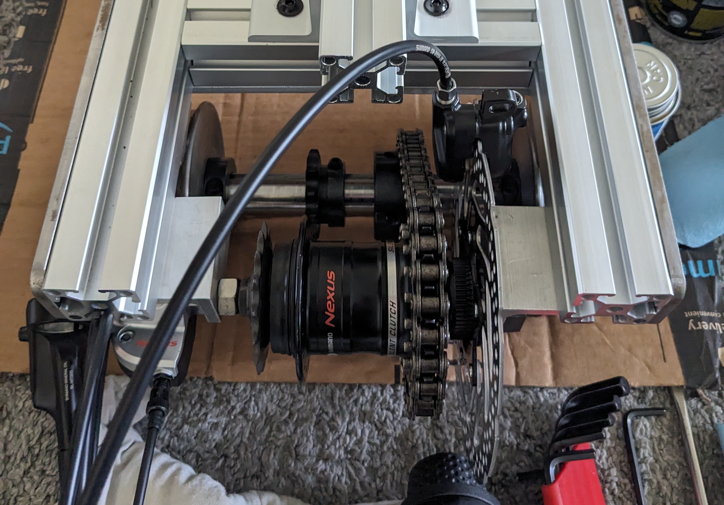
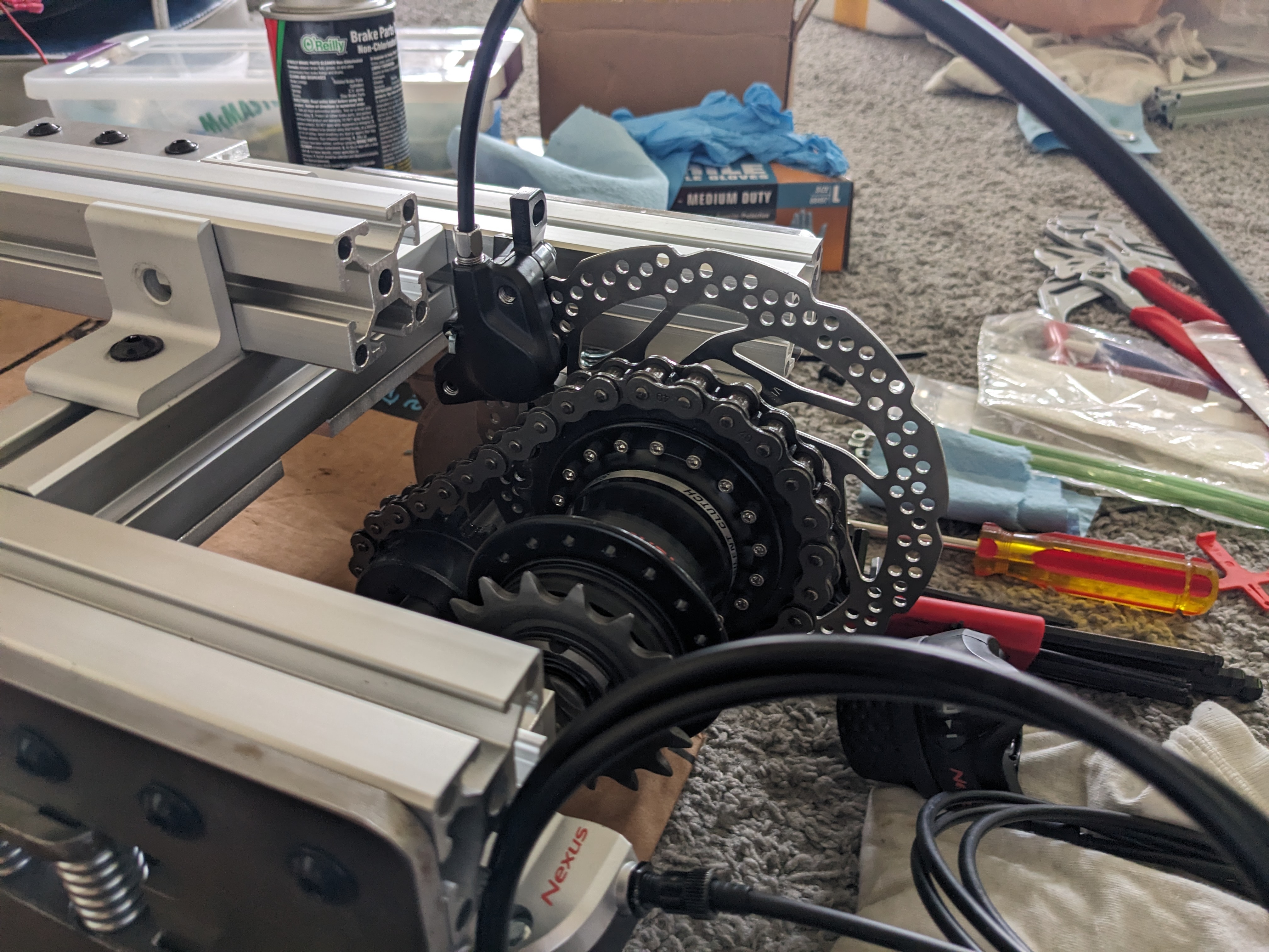
In order to transfer the output torque of the hub to the output chain, I needed to fix a sprocket to the hub. I was able to machine out the center of a large flat sprocket using another conversational CNC mill, and then drill and tap holes which matched the holes in the hub’s flange intended for bicycle wheel spokes.
For reference, the sprocket tooth counts are as follows. These sprockets are sized to prioritize torque output.
- Motor output: 44 (Bicycle single speed chain)
- Hub input: 16 (Bicycle single speed chain)
- Hub output: 24 (ANSI 40 chain)
- Axle input: 17 (ANSI 40 chain)
- Axle to axle link: 12 (ANSI 40 chain)
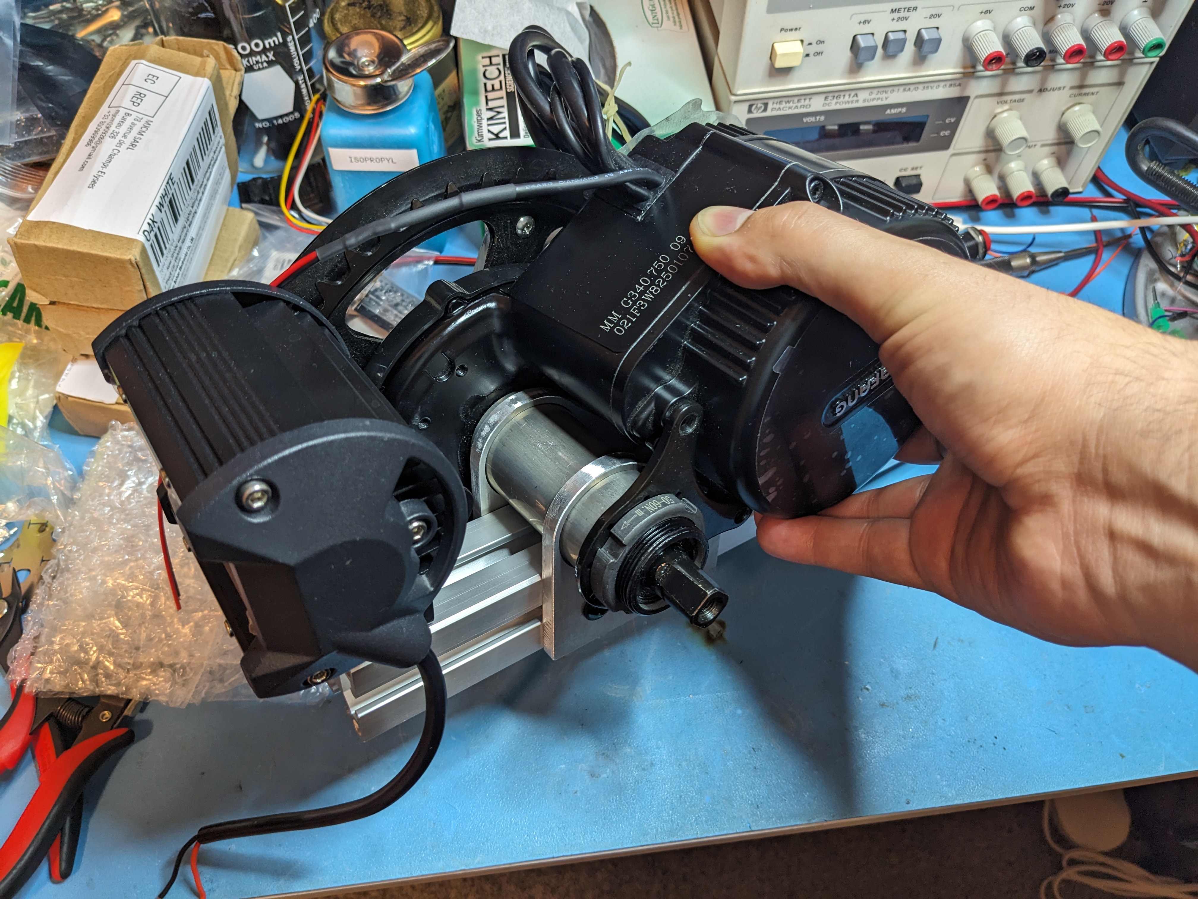
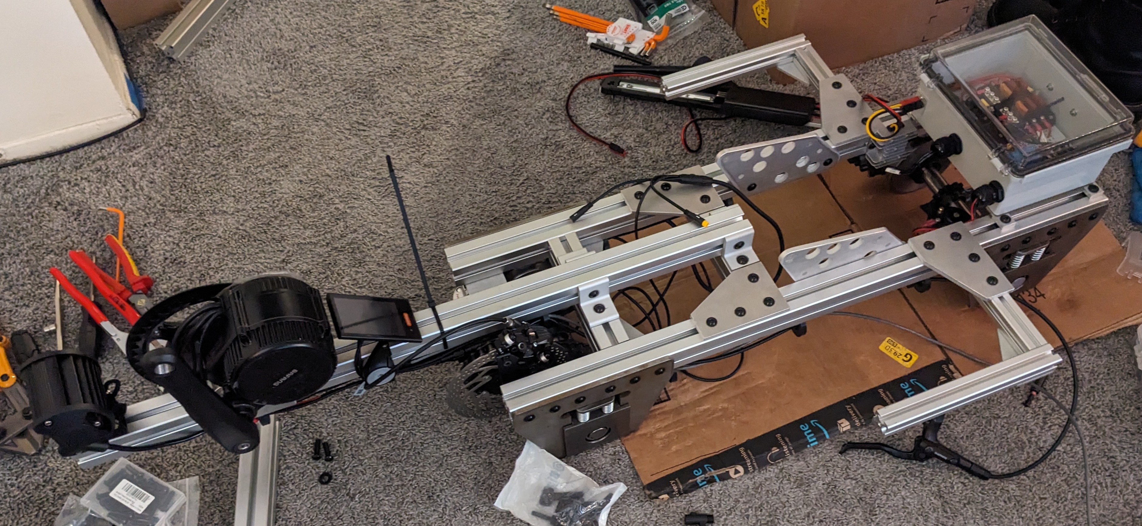
The motor was mounted upside-down from the typical bicycle configuration using a couple of waterjet plates and a piece of tube which were later TIG welded together. This mockup on a short piece of extrusion also has an “18W” (they’re really 12W) off-roading spotlight which will serve as a headlight.
With the motor mount completed, the train is looking mostly complete. Note that I had to use aftermarket 140mm crank arms rather than the stock 152mm crank arms to accommodate for the ergonomics of the motor to seat positioning.
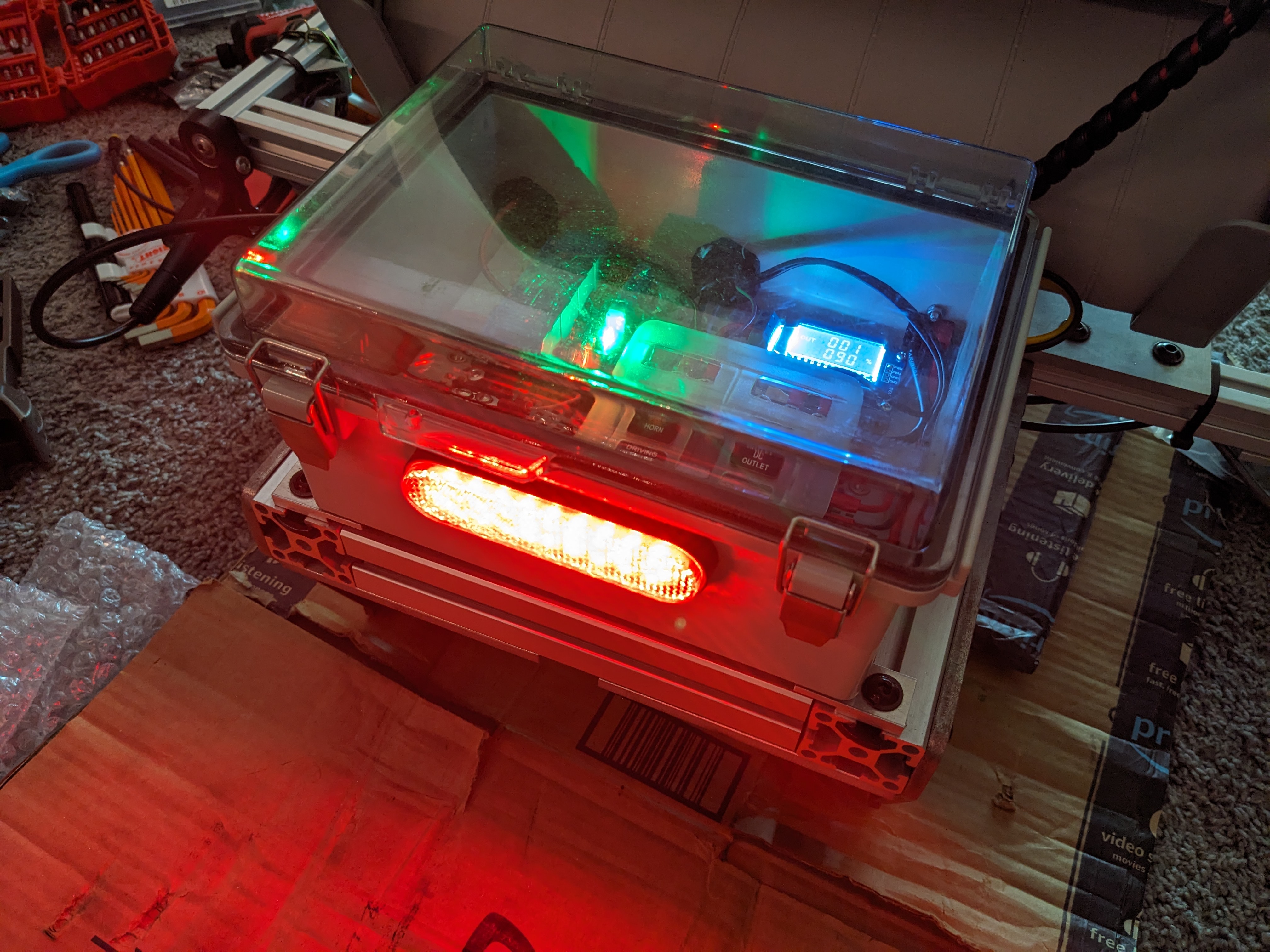
The Bafang BBS02 motor actually integrates the motor drive electronics into the motor assembly, simplifying wiring considerably. The motor takes 48V directly from the 15Ah 13S3P 21700 Li-ion battery pack, and a second 48V feed was wired to a small DC/DC converter is used to generate 12V accessories. The box on the end of the frame contains 12V fusing, switching, and distribution for things like the headlight, horn (a small motorcycle horn), phone charger, and FRED. A FRED is a Flashing Rear End Device which is often required for operating scale trains at night, so I implemented one directly on the locomotive using a cheap motorcycle brake light and a digital PWM generator module.
Some zip ties and a boat seat later, and the McMaster-Car is ready for a test run!
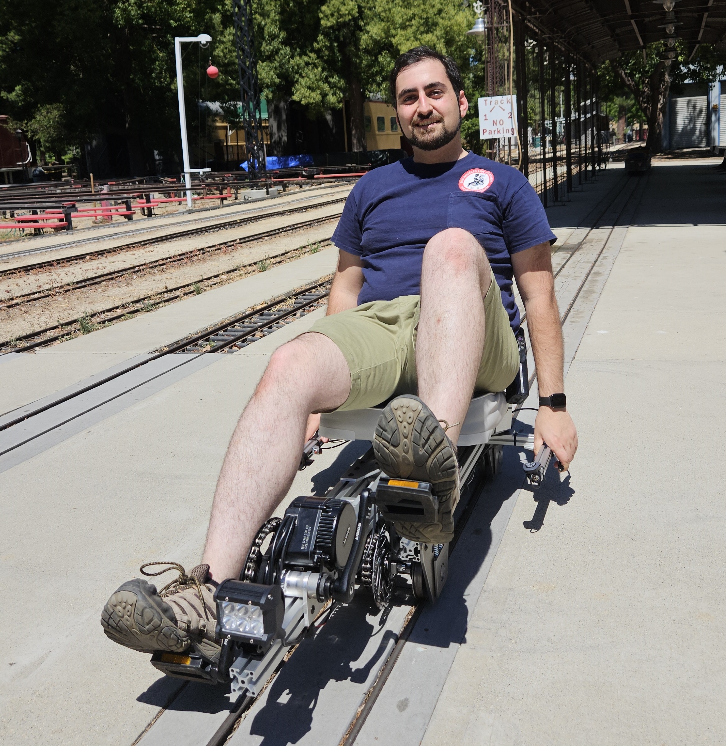
It’s quite a blast to zoom around the LALS track. I hope to continue to make updates to the McMaster-Car as I have time. Some major updates include a coupler and an airbrake system for use with various riding cars, and minor updates include things like adding cup holders for a water bottle or radio, and making the handles a bit more ergonomic.
Here’s almost 10 minutes of unedited footage of a loop around the LALS track if you’re craving a soundtrack for rereading this post.
