
Motorola XPR 4000 Series Audio Repair
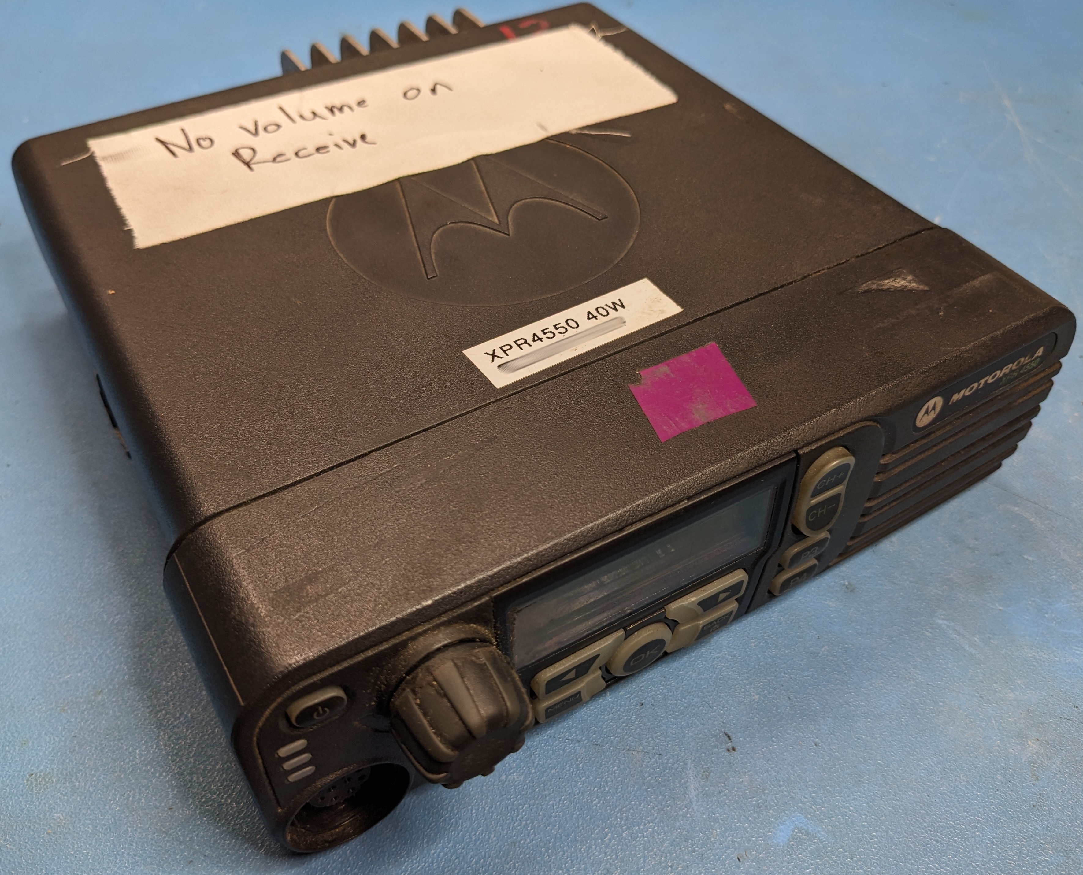
A somewhat common issue with these radios is losing all audio. If a unit’s built-in speaker doesn’t make a pop sound or power-on tone when powered on — and the codeplug checks out fine — the audio amplifier has likely failed.
Here is a block diagram of the audio path within the XPR 4000 series of mobiles, taken from the detailed service manual.

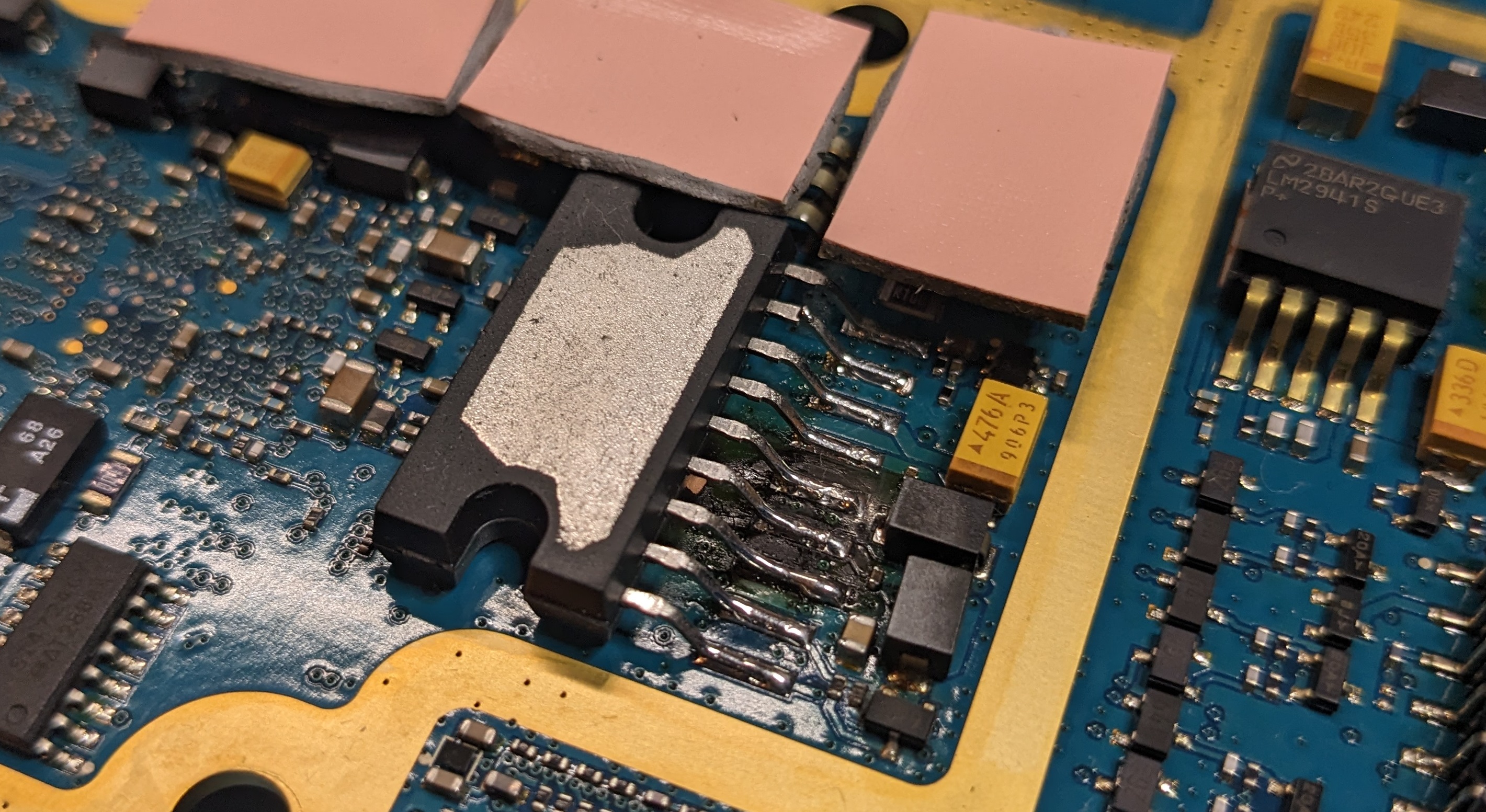
The culprit is U3500, the TDA1519C final audio amplifier IC. It seems that there’s some issue causing these amplifiers to fail at a non-negligible rate in these radios. Per the datasheet, these ICs have internal thermal protection, so it’s unlikely that the problem is simply poor thermal contact with the heatsink. Perhaps an edge-case turn-on transient causes some kind of violent instability like shoot-through? The radios I’m repairing were used to drive an intercom system, which shouldn’t present much of a load to the amplifier output.
Unfortunately, the TDA1519C is discontinued. Thankfully, there are still a handful of grey-market parts available from the usual suspects.
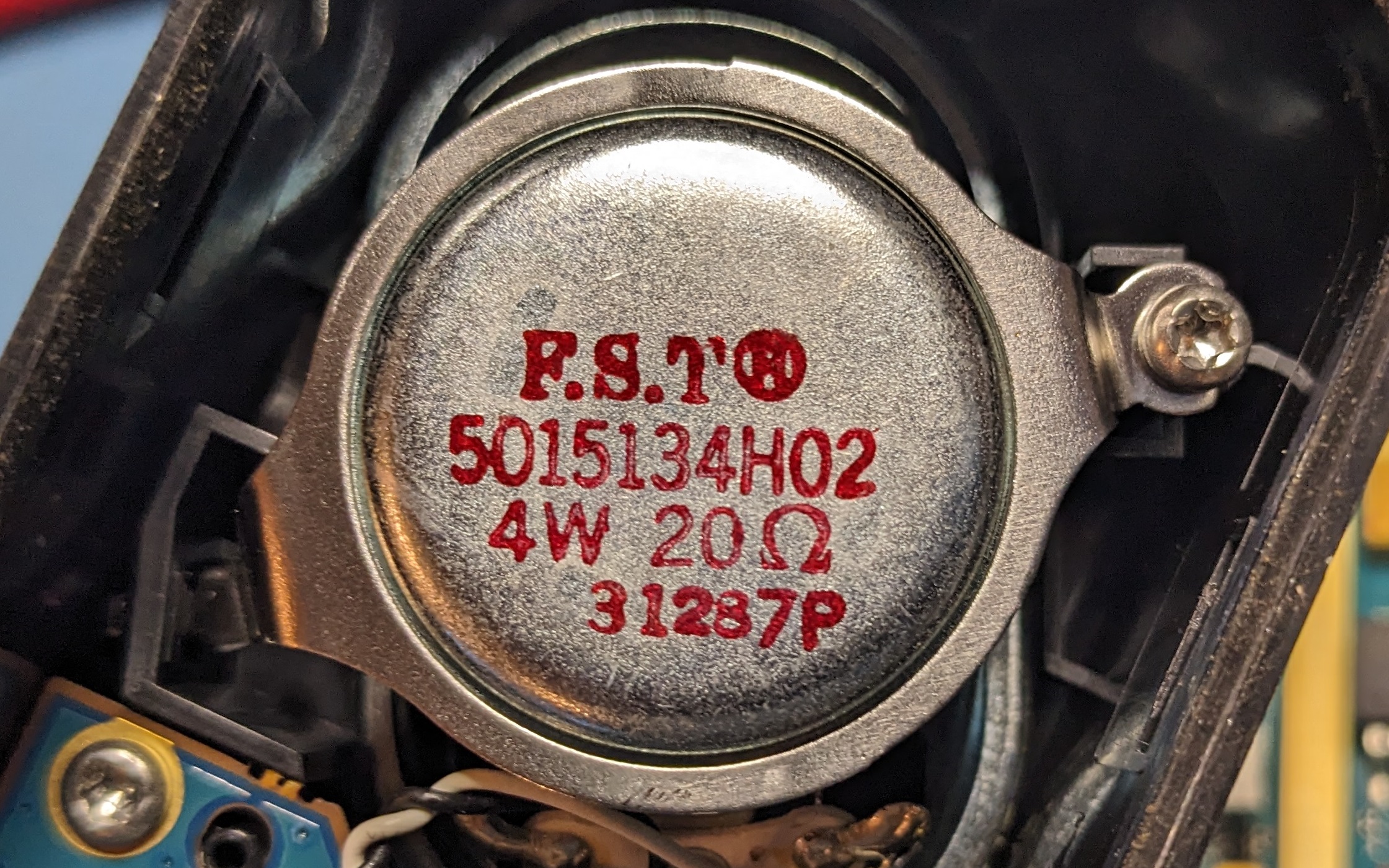
Note that in some cases this failure seems to result in damage to the front speaker built in to the radio’s front panel. Replacement parts can be found online.
Disassembly
First, remove the outer plastic cover/jacket. This is done by simply prying it to the sides.

At this point, you should probably remove the control head before removing the lid and exposing the PCB. Do as I say, not as I do and all that. The control head must be pried off, and one or two ribbon cables disconnected from the main PCB depending on the options in a particular unit. Do not leave any ribbon cables connected to the main board, as we’ll be removing it from the enclosure.
Remove the seven fasteners with a T20 driver. Note that each screw has an o-ring that must be reinstalled between the body and the lid prior to reinsertion. Some units that have been serviced previously might not have these o-rings.

Now remove the lid to expose the PCB.

To remove the PCB:
- Remove the MAP accessory connector (black plastic housing with 0.1” pins on the rear of the unit) by pulling it out the back. The only thing retaining it is the friction of the contacts and gasket.
- Disconnect the internal GPS antenna cable.
- Remove the two retaining clips on the power and mini UHF connectors. These can be pulled off with pliers and a gentle side-to-side wiggle. Be careful not to damage the PCB during this step! It’s easy to slip and damage traces or components.

Now the PCB can be tilted up and removed from the housing. Immediately upon lifting the board, you’ll likely notice the unmistakable smell of fried electronics if the audio amplifier has failed. Before even flipping over the PCB, you may see residue on the housing near the amplifier.

Turning the PCB over, the audio amp is located on the left side of the board.

Inspecting multiple units, the audio amplifier seems to fail catastrophically and consistently in the same way.

Examining the Circuit
It seems that the same pins are damaged across units.

These correspond to the pins shown in the TDA1519C datasheet.

The suggested implementation in the datasheet matches the circuit used in the XPR 4000 series, per the detailed service manual sheet 124.


Repair
Rather than trying to desolder and remove the IC in one go, I suggest snipping the remaining leads with small wire cutters, then desoldering the individual pins. Done carefully, this stresses the PCB less than trying to desolder the entire chip at once.
Sometimes the leads are nice enough to vaporize themselves, so you don’t even have to cut them!

After desoldering and wicking the remaining solder, inspect the pads for damage. In two of the three units I repaired, the pads were fine, but in the worst unit, the pin 7 “Vp” pad seemed to have sacrificed itself as a fuse.

Install the new part.
If you’re feeling like being extra thorough, you might also replace the thermal pad between the audio amp IC and the enclosure. The stock pad is 1mm thick, and about 12 x 20mm. Any generic 1mm pad can be cut to size and used in this application. Thermal paste should probably also be applied to the two ICs on the bottom side of the board which use thermal paste rather than a gasket.
Be sure to clean the PCB and enclosure before reassembly. The nearby thermal pad/adhesive often has gunk embedded in it from the explosion in failed units — check yours carefully. We wouldn’t want a piece of FOD causing more issues.

Reassemble in reverse order of disassembly.
Resources
- TDA1519C Datasheet - NXP
- Service Manual (UHF) - Magnum Electronics
- They also maintain an extensive modern Batwing document library with many full service manuals.
- Video of technician performing this repair on an XPR 4550 - Blue Mountain Radios on YouTube