VGA to Oscilloscope (XYZ) Converter
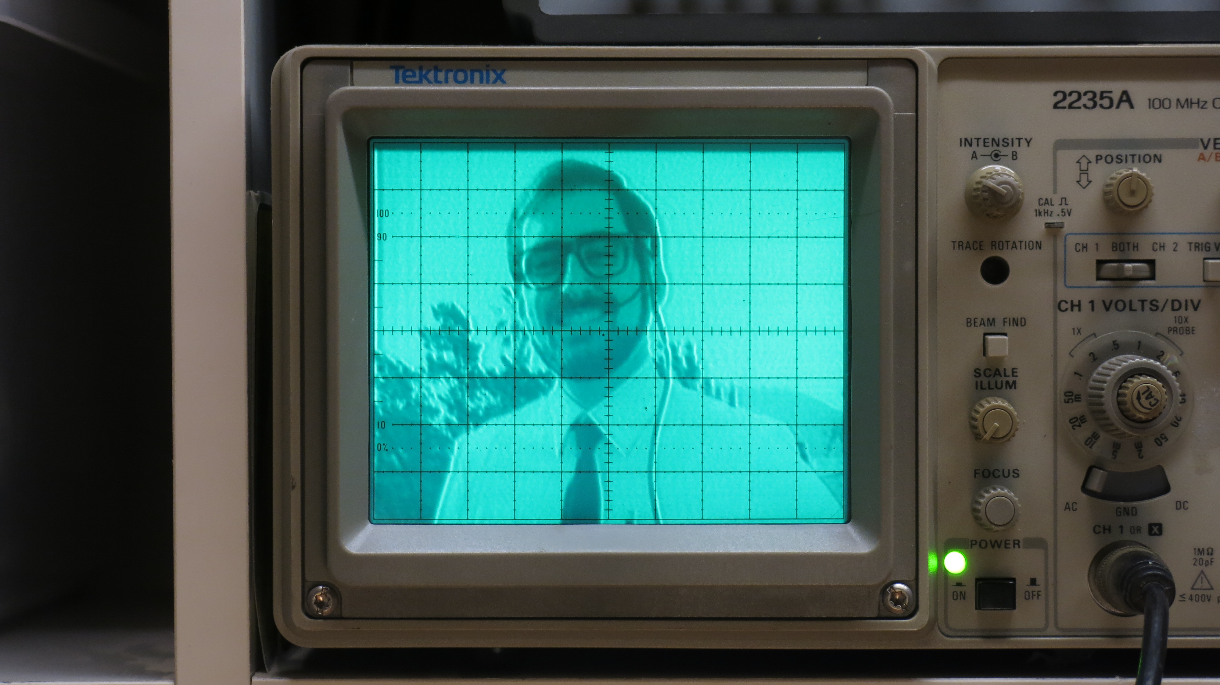
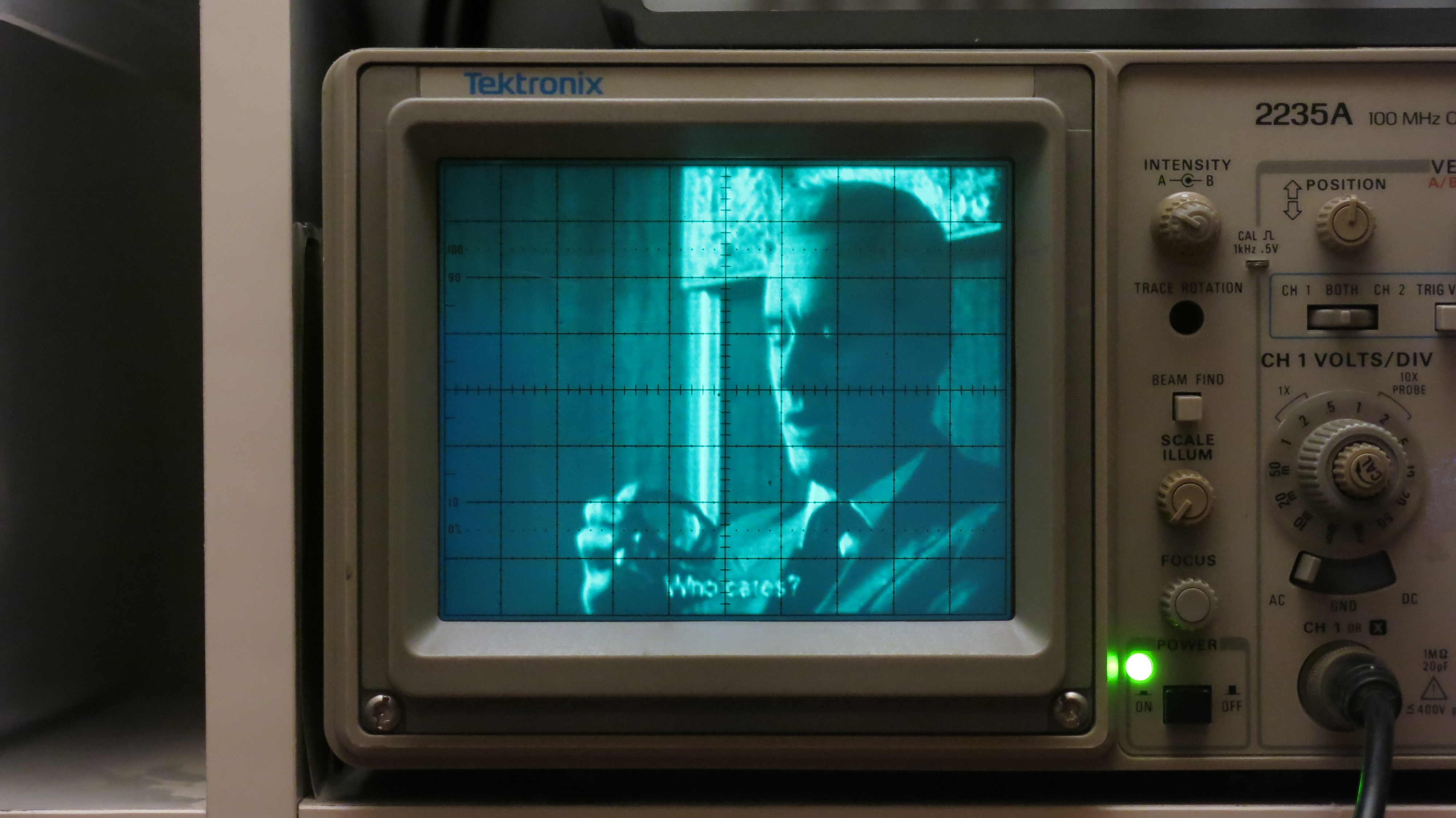
A few years ago, I built some hardware to allow an oscilloscope to be used as a VGA display. I often use the photo above as my profile/avatar online and get asked why there are crosshairs on me… here’s how it works!
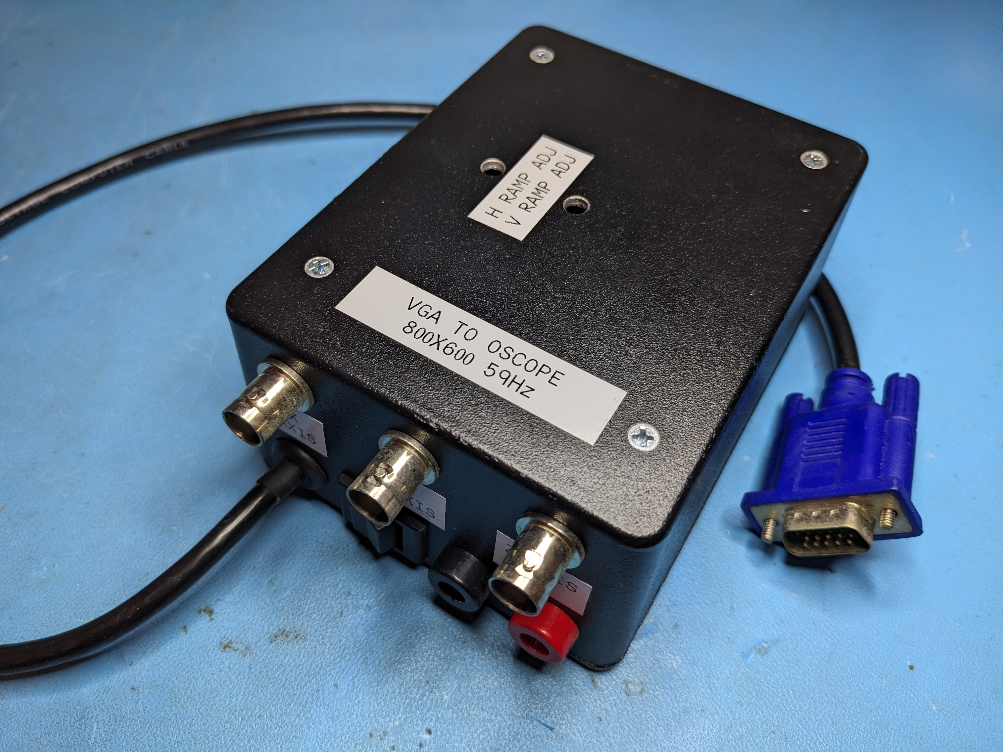
Not to delve too far into the VGA signalling standard, but it’s essentially meant to drive cathode ray tube (CRT) monitors in as simple of a way as possible using a few analog and digital signals. A VGA monitor receives a set of horizontal and vertical synchronization pulses which are used to drive the electron beam across the screen in order to draw the desired image, while red, green, and blue analog signals control the display of colors as the beam makes its way along the screen. The circuitry needed to parse the VGA signals and control a basic CRT like that of an old oscilloscope can be implemented with a few basic ICs.
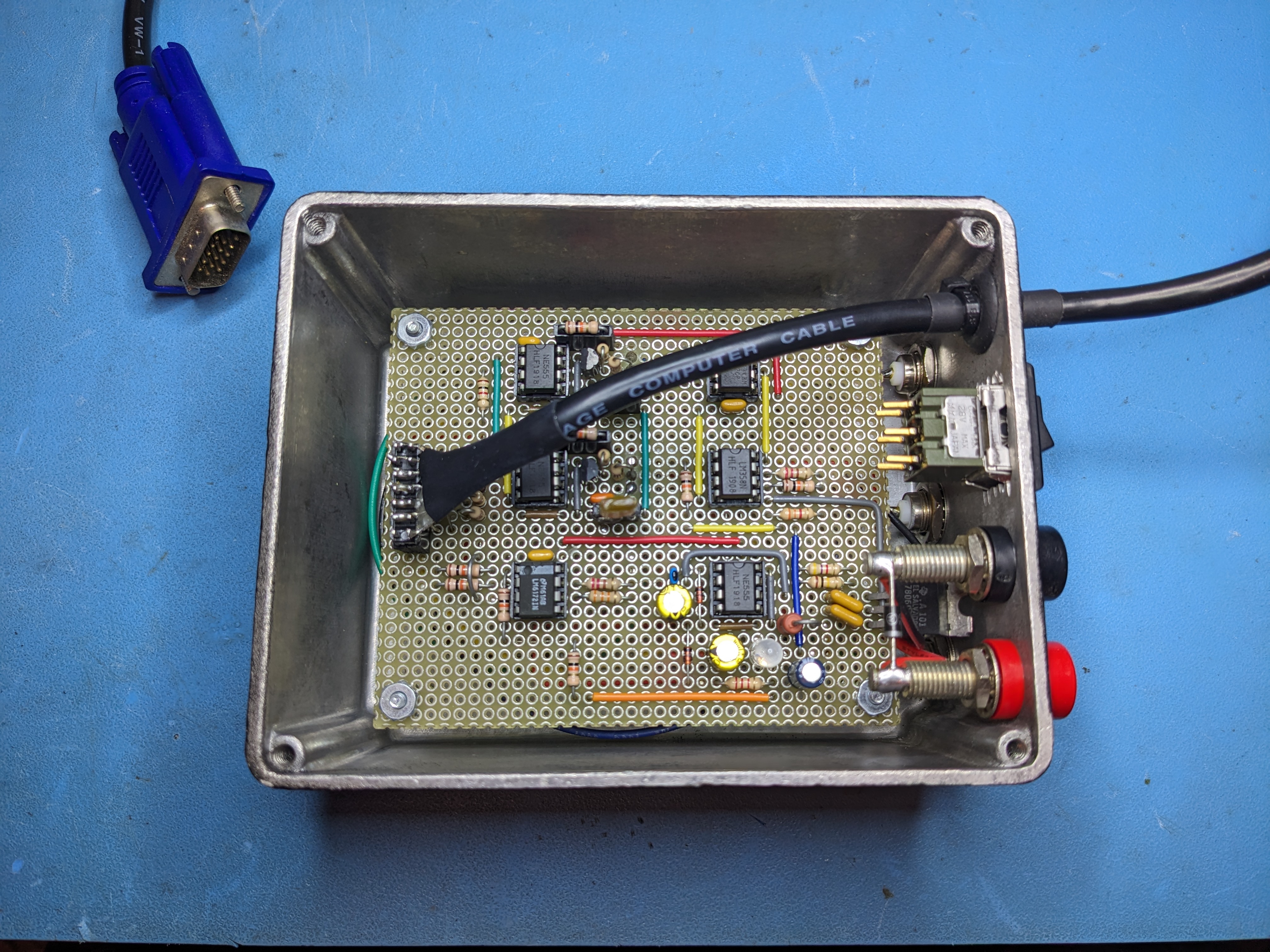
The photo above shows the relatively simple circuit implementation using a handful of op-amps and 555 timer ICs. The original circuit comes from Jon Stanley’s fantastic site which has a plethora of interesting and very well documented electronics projects.
Was this a waste of my time?