
Weigl ProCommander4 Hardware Teardown
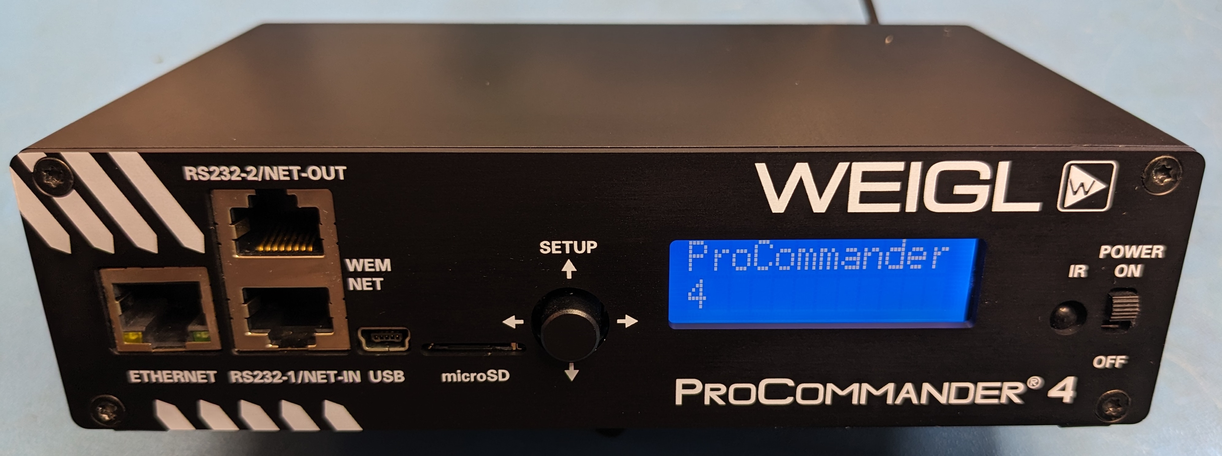
The Weigl ProCommander4 show controller crossed my path recently, and curiosity got the better of me.
Weigl Control makes show control equipment for professional and prosumer applications. This is a look at the ProCommander4’s hardware — what’s on the board, how the pieces fit together, and what that tells us about how it works.
Rear Panel
The rear panel is where the ProCommander4 connects to the outside world — power in, control signals out, and the interfaces for show control. While the network interface is located on the front panel, the rear panel provides serial interfaces for show control, digital inputs and outputs, servo outputs, analog outputs, and a loudspeaker line out for audio. These connections enable the ProCommander4 to integrate seamlessly into complex animatronic systems.

PCB — Top View
The main board is where all the interesting work happens. The key ICs are labeled below.

AT32UC3A1512 — Main MCU
The central processor is an Atmel (now Microchip) AT32UC3A1512, a 32-bit AVR32 microcontroller running at up to 66 MHz with 512 KB of flash and 64 KB of SRAM. The AVR32 UC3 family was Atmel’s high-performance embedded controller line, and the A1512 variant includes a full-speed USB device/host controller, a 10/100 Ethernet MAC (used here in conjunction with the external W5100 PHY/stack), SPI, I²C, USART, and a hardware DMA controller. This is the chip executing the show file decoding loop — reading cue data, generating output timing, and coordinating all the peripheral ICs.
W5100 — Ethernet
The WIZnet W5100 is a hardwired TCP/IP stack chip — it handles Ethernet entirely in hardware, so no network stack software runs on the MCU.
VS1053b — Audio Codec
The VLSI VS1053b is a single-chip audio codec that handles decoding of MP3, OGG Vorbis, AAC, WMA, FLAC, WAV, and MIDI. It takes compressed audio from the MCU over SPI and outputs an analog stereo signal.
TPA3123D2 — Class D Amplifier
The TI TPA3123D2 is a 25 W per channel class D audio power amplifier. It takes the analog stereo output from the VS1053b and drives speakers directly. Class D was the right choice here — it’s efficient enough that no heatsink is required in a sealed enclosure at typical animatronic audio levels. The TPA3123D2 operates from a single supply (10–36 V) and includes short-circuit and thermal protection.
SN75LBC176 — RS-485 Transceiver
The SN75LBC176 (equivalent to SN65LBC176) is a differential bus transceiver for RS-485 and RS-422 networks — the electrical interface for DMX output.
MC34063A — DC/DC Converter
The MC34063A is a classic, minimal switching regulator controller containing an oscillator, comparator, and switch transistor in a single package. It is used here to generate one of the internal supply rails from the input power — most likely stepping down the incoming DC to a lower logic voltage. The MC34063A dates to the 1970s and remains in production; its simplicity makes it a frequent choice when a secondary rail doesn’t need high efficiency or tight regulation.
WH1202A — Character LCD
The Winstar WH1202A-TMI-ET# is a 1.6″ 12×2 character LCD module with a built-in ST7066 HD44780-compatible controller — the LCD interface for the unit. The MCU talks directly to the ST7066 on the module.
DS3911 — Analog Output DAC
The DS3911 (Analog Devices / Dallas Semiconductor) is a quad-channel, 10-bit I²C DAC. Its outputs are routed through a set of LM358 op-amps configured as scaling amplifiers, which bring the DAC’s native output range up to 0–10 VDC on the rear connector.
MCP79411 — Real-Time Clock
The Microchip MCP79411 is a battery-backed I²C real-time clock/calendar (RTCC) with 64 bytes of SRAM and a unique ID ROM. Its presence here ensures the ProCommander4 maintains accurate time even when powered off — relevant for any show scheduling, logging, or time-stamped event triggering the firmware implements. The I²C interface keeps the pin count minimal; the battery backup means the clock continues running through power cycles without requiring NTP or user re-entry of the time. A coin cell battery holder is present on the PCB — empty in this unit, but the footprint is there and ready.
The underside of the board is largely solder and passive components, but one feature is worth noting.

TPA3123D2 Thermal Management
The exposed copper pad visible on the bottom of the board — tinned with solder — is the thermal relief for the TPA3123D2 class D amplifier directly above it on the top side. Class D amplifiers are efficient but still dissipate heat at the drive currents used for speakers — the TPA3123D2’s package includes a large exposed metal pad on the underside of the IC itself, which solders directly to the PCB and conducts heat into the board’s copper pour, letting the PCB act as the primary heat dissipator. In a sealed enclosure like this one, conducting heat into the chassis ground plane is the practical alternative to an external heatsink.
PCB — Network and Playback Region
Zooming into the front-left quadrant of the board brings the network and audio subsystem into focus.

ST232C — RS-232 Transceiver
The STMicroelectronics ST232C is a pin-compatible alternative to the classic Maxim MAX232 — a dual-driver, dual-receiver RS-232 transceiver that generates the ±7.8 V RS-232 signal swings from a single 5 V supply using an internal charge pump and four external capacitors. Finding this alongside the SN75LBC176 RS-485 transceiver means the ProCommander4 has two separate serial port standards: RS-485 for robust multidrop field connections to animatronic figures running over long cable distances, and RS-232 for shorter-range point-to-point use.
LM358 — Analog Output Scaling
The LM358 dual op-amps visible in this region are configured as scaling amplifiers in the analog output path — they sit between the DS3911 DAC and the rear D-sub connector, amplifying the DAC’s native output up to the 0–10 VDC range expected by industrial equipment.
Audio Outputs — Line Out and Speaker Terminals
The board exposes two audio output paths. The 3.5mm stereo line-out jack provides a line-level signal taken directly from the VS1053b DAC output, bypassing the power amplifier entirely — useful for connecting to an external amplifier, mixer, or audio distribution system in larger installations. The speaker screw terminals are the direct-drive output of the TPA3123D2 class D amplifier, intended for connecting 4Ω or 8Ω speakers directly at the enclosure. Having both outputs populated means the same unit can serve either as a self-contained speaker driver or as an audio source node in a larger show audio system.
System Architecture
Putting it all together, the block diagram below shows how the major components interconnect. The AT32UC3A1512 sits at the center, coordinating every subsystem over SPI, I²C, and UART.
graph LR
    classDef mcu fill:#e8985c,stroke:#333,color:#fff,font-weight:bold
    classDef ic fill:#f5f0eb,stroke:#999,color:#333
    classDef conn fill:#dcedc8,stroke:#558b2f,color:#333,stroke-width:2px
    classDef generic fill:#e3f2fd,stroke:#1565c0,color:#333,stroke-width:2px,stroke-dasharray:5 5
    classDef storage fill:#fff3e0,stroke:#e65100,color:#333,stroke-width:2px
    classDef display fill:#ede7f6,stroke:#4527a0,color:#333,stroke-width:2px

    SD([Micro SD Card]):::storage <-->|SPI| MCU[AT32UC3A1512]:::mcu
    MCP79411:::ic <-->|I2C| MCU
    LCD[WH1202A]:::display --- ST7066:::ic <-->|Parallel| MCU
    ETH([RJ45 Ethernet]):::conn --- W5100:::ic -->|SPI| MCU
    RJ45RS([RJ-45 RS-232]):::conn --- ST232C_2[ST232C]:::ic <-->|UART| MCU

    MCU -->|SPI| VS1053b:::ic
    VS1053b -->|Analog| TPA3123D2:::ic
    VS1053b -->|Analog| LINEOUT([3.5mm Line Out]):::conn
    TPA3123D2 --> SPKR([Speaker Terminals]):::conn
    MCU -->|UART| SN75LBC176:::ic
    SN75LBC176 --> DMX([5-Pin DMX I/O]):::conn
    MCU <-->|UART| ST232C_1[ST232C]:::ic
    ST232C_1 <--> DB9([DB-9 RS-232]):::conn
    MCU -->|SPI| HC595["74HC595 (x2)"]:::ic
    HC595 --> DOUT([Digital Outputs]):::generic
    MCU <-->|SPI| HC165[74HC165]:::ic
    HC165 --> DINP([Digital Inputs]):::generic
    MCU -->|I2C| DS3911:::ic -->|Analog| LM358:::ic
    LM358 -->|0-10V| AOUT([Analog Outputs]):::conn
Design Notes
Overall the ProCommander4 is a logical, well-considered piece of hardware. The component choices make sense — each part does a clearly defined job, the interconnections are straightforward, and the result is a low parts count design that appears to work reliably. Nothing here is cutting-edge, but that’s fine; this kind of equipment benefits far more from proven parts and predictable behavior than from chasing the latest silicon.
If I had one manufacturing note, it would be around mechanical robustness. Several of the larger through-hole components — electrolytic capacitors, the input ferrite bead — are unsupported beyond their solder joints and sit freestanding above the board. In most installation environments that’s probably fine, but for a piece of equipment at this price point, a small amount of silicone staking on those components would go a long way toward preventing joint fatigue from vibration over time.
The LCD module and the front-panel 5-way joystick switch both sit on small sub-PCB assemblies that protrude from the front of the unit with no additional mechanical support. These are the kinds of connections that don’t take much force to damage — the copper can lift from the substrate before you’ve applied what feels like significant load. Staking both of those assemblies at the base would make them considerably more robust and is the kind of detail that separates a good product from a great one.
None of this is a serious criticism — it’s a sensible, functional design that clearly does what it’s supposed to do.
Disclaimer
This analysis is based entirely on visual inspection of photographs — no firmware was extracted, no signals were probed, and no schematic was available. The interconnections shown in the block diagram above are inferred from datasheet-typical usage patterns and the physical proximity of components on the PCB, not from verified traces. Some assumptions are almost certainly wrong.
This is purely a hobbyist exercise in reverse-engineering curiosity — meant to help others understand how a piece of show control hardware is put together at a high level. It is not a competitive analysis, not an attempt to replicate or undermine Weigl’s product, and not a criticism of their engineering. Weigl Control makes solid equipment, and the goal here is appreciation, not deconstruction.