
Gilderfluke 3.5mm RS-232 Adapter
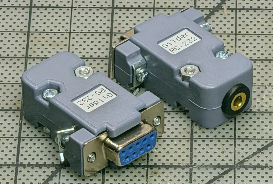
Gilderfluke devices use a 3.5mm TRS jack for RS-232 communication. The combination of a bulky D-Sub connector and a thin pigtail cable is not ideal for carrying around — a minor annoyance, but one I decided to solve. This simple passive adapter converts a DB9 to a 3.5mm jack, so I can use any off-the-shelf audio cable for the run to the device instead.
Background
This is not a particularly groundbreaking build. Gilderfluke show controllers like the Sd-50 accept RS-232 over a 3.5mm TRS connector, while most USB-to-serial adapters terminate in a DB9. You can buy a pre-made cable from Gilderfluke, or take an existing DB9 pigtail cable and solder a 3.5mm plug onto the end. Either way, the result is a floppy cable with a comparatively large D-Sub on one end — not the most elegant solution.
A blocky adapter with a 3.5mm jack on one end and a DB9 on the other solves this for me. I can keep the adapter attached to my serial adapter and use a standard 3.5mm audio cable of whatever length I need. The cable stores separately, and the adapter body is small enough to toss in a bag without worrying about snagging or straining the conductors.
Pinout
The Sd-50 manual defines the RS-232 pinout on the 3.5mm connector as follows:
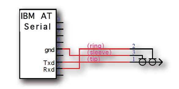
The mapping to the DB9 is straightforward — only three conductors are needed:
3.5mm TRS       DB9 (DCE)    Signal
─────────────   ─────────    ──────
Tip              Pin 3       TXD
Ring             Pin 2       RXD
Sleeve           Pin 5       GND
No flow control lines are used; this is a minimal three-wire RS-232 connection.
Construction
The adapter consists of a female DB9 solder-cup connector and a panel-mount 3.5mm TRS jack, wired together with short lengths of hookup wire and housed in a DB9 backshell.
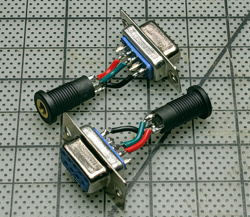
I soldered the three conductors to the appropriate DB9 pins and 3.5mm jack terminals, keeping the leads short to fit inside the backshell. The backshell is used as-is — the only modification needed is widening the cable entry hole to accept the 3.5mm jack body.
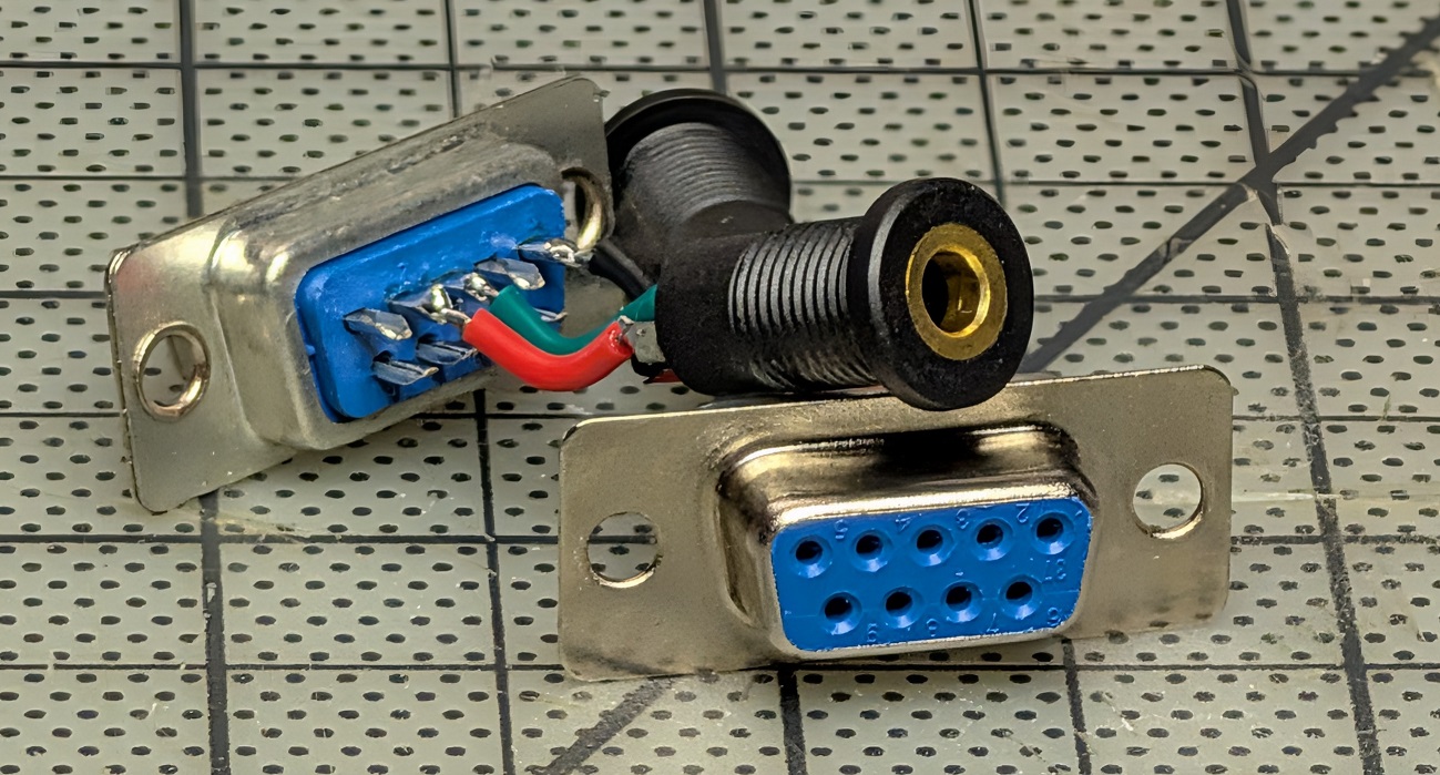
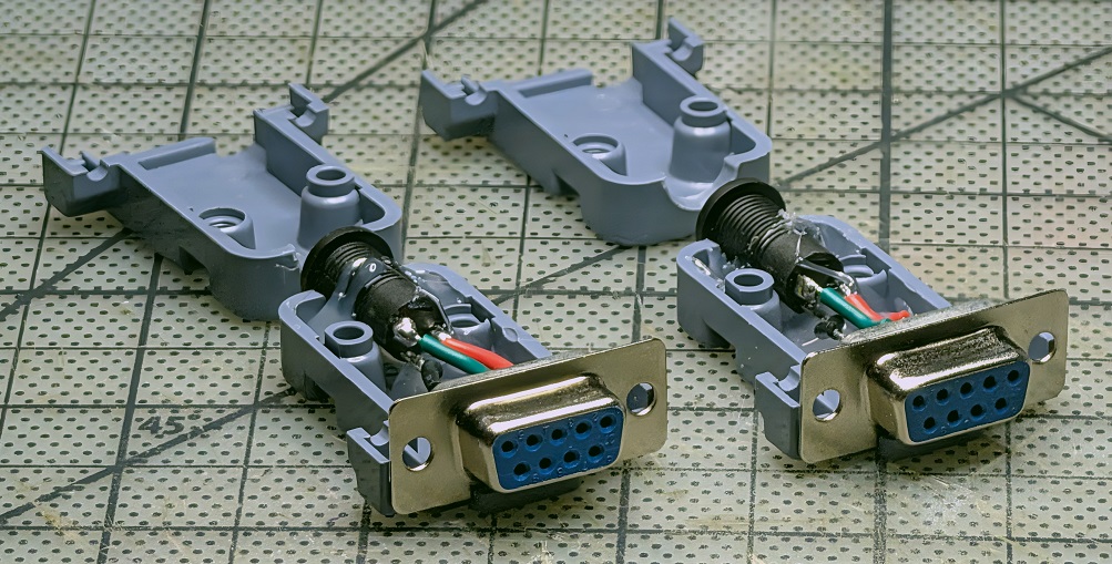
The 3.5mm jack fits through the widened cable entry of the backshell and is secured in place with hot glue. The whole assembly closes up into a compact block.